 |
The FALCON-E, Instruction Set Architecture Comparison |
| << Behavioral Register Transfer Language for FALCON-A, The EAGLE |
| CISC microprocessor:The Motorola MC68000, RISC Architecture:The SPARC >> |
Advanced Computer
Architecture-CS501
Computer
Architecture
Lecture
No. 10
Reading
Material
Handouts
Slides
Summary
3) The
FALCON-E
4)
Instruction Set Architecture
Comparison
THE
FALcON-E
INTRODUCTION
FALCON
stands for First
Architecture for Learning
Computer Organization and
Networks.
We are already familiar with
our example processor, the
FALCON-A, which
was the
first version of the FALCON
processor. In this section we will
develop a new
version
of the processor. Like its
predecessor, the FALCON-E is a
General-Purpose
Register
machine that is simple, yet
is able to elucidate the fundamentals of
computer
design and
architecture.
The
FALCON-E is characterized by the
following
· Eight
General Purpose Registers (GPRs), named
R0, R1...R7. Each registers is 4
bytes
long (32-bit
registers).
· Two
special purposes registers, named BP and SP. These
registers are also 32-bit
in
length.
· Two
special registers, the Program Counter
(PC) and the Instruction
Register
(IR). PC
points to the next
instruction to be executed, and the IR
holds the current
instruction.
· Memory
word size is 32 bits (4
bytes).
· Memory
space is 232
bytes
· Memory
is organized as 1-byte
cells,
and hence it is 232 x 8
bits.
· Memory
is accessed in 32-bit
words
(4-byte chunks, or 4
consecutive
cells)
· Byte
storage format is
little
endian.
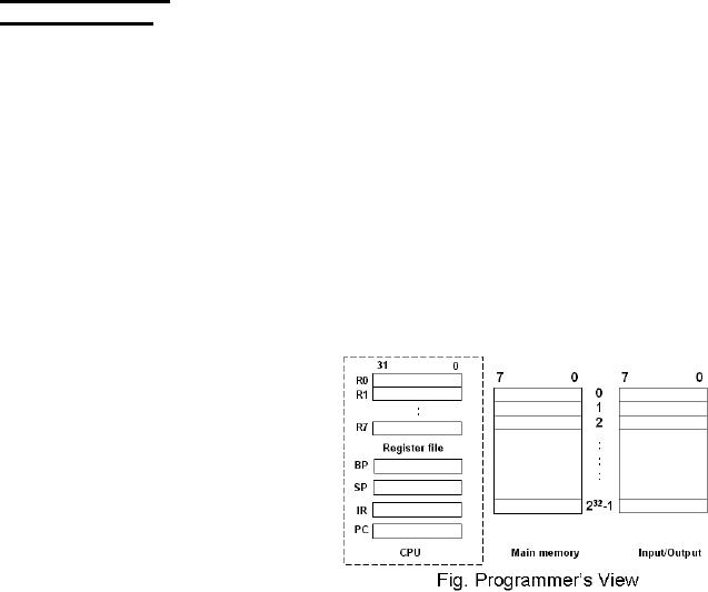
Programmer's
view of the FALCON-E
The
programmer's view of the
FALCON-E is shown in the
given figure.
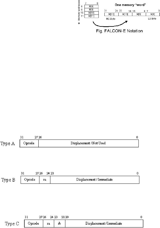
FALCON-E
Notation
We take a
brief look at the notation
that we will employ for the
FACLON-E.
Register
contents are
referred to in a similar fashion as
the FALCON-A, i.e. the
register
name in
square brackets. So R[3] means
contents of register
R3.
Page
125
Last
Modified: 01-Nov-06
Advanced Computer
Architecture-CS501
Memory
contents (or
the memory
location)
can be referred to in a similar
way.
Therefore, M[8] means
contents
of memory
location 8.
A memory
word is stored in
the
memory in
the little endian
format.
This
means that the least
significant
byte is
stored first (or the little
end comes first!). For
instance, a memory word at
address
8 is
defined as the 32 bits at
addresses 11, 10, 9, and 8
(little-endian). So we can employ
a
special
notation to refer to the
memory words. Again, we will
employ as the
concatenation
operator. In our notation
for the FALCON-E, the
memory word stored at
address 8
is represented as:
M[8]<31...0>:=M[11]©M[10]©M[9]©M[8]
The
shown figure will make this
easier to understand.
FALCON-E
Features
The
following features characterize
the FALCON-E
· Fixed
instruction size, which is 32
bits. So the instruction size is 1
word.
· All ALU
instructions have three
operands
· Memory
access is possible only through
the load and store instructions.
Also, only
a limited
addressing modes are supported by
the FALCON-E
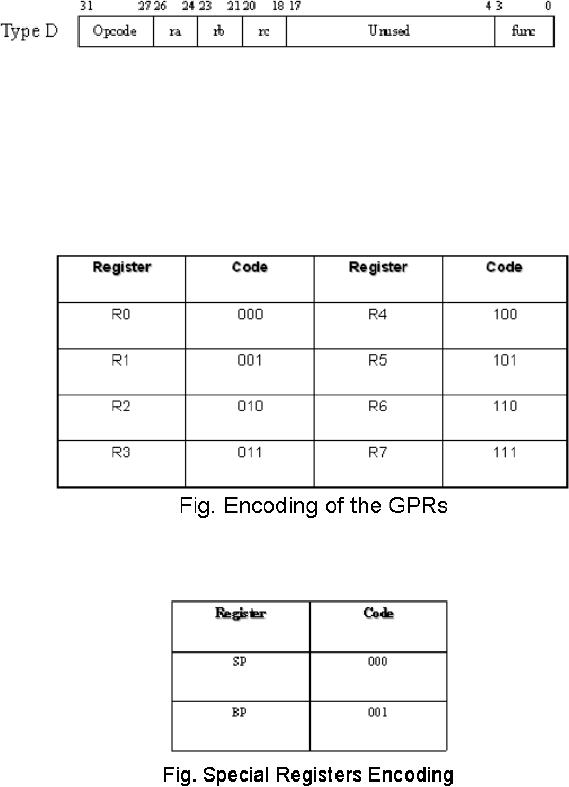
FALCON-E
Instruction Formats
Four
different instruction formats
are supported by the
FALCON-E. These are
Type
A instructions
The
type A instructions have 5
bits reserved for the
operation code (abbreviated
op-code),
and the
rest of the bits are either
not used or specify a
displacement.
Type
B instructions
The
type B instructions also have 5
bits (27 through 31)
reserved for the op-code.
There
is a
register operand field, ra, and an
immediate or displacement field in
addition to the
op-code
field.
Type
C instructions
Type C
instructions have the 5-bit
op-code field, two 3-bit operand
registers (rb is the
source
register, ra is the destination
register), a 17-bit immediate or
displacement field, as
well as a
3-bit function field. The
function field is used to
differentiate between
instructions
that may have the
same op-code, but different
operations.
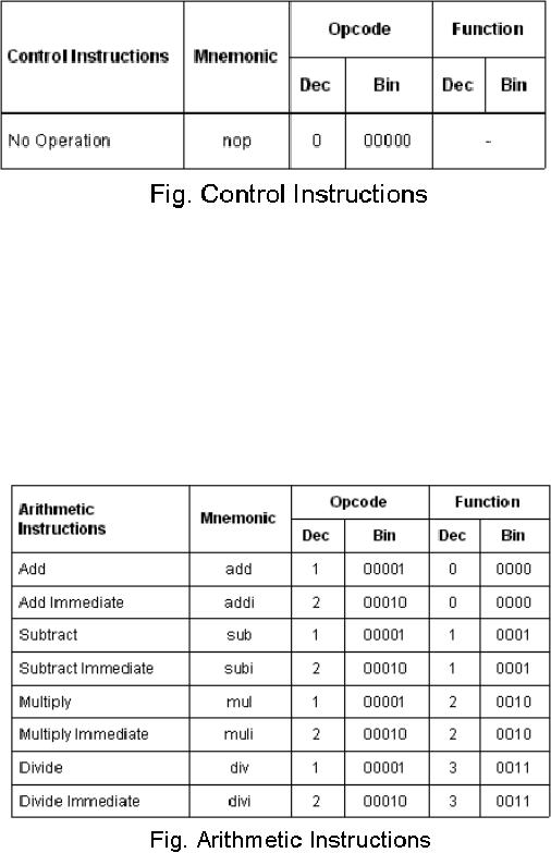
Type
D instructions
Type D
instructions have the 5-bit
op-code field, three 3-bit operand
registers, 14 bits are
unused,
and a 3-bit function
field.
Page
126
Last
Modified: 01-Nov-06
Advanced Computer
Architecture-CS501
Encoding
for the General Purpose
Registers (GPRs)
In the
instruction formats discussed
above, we used register
operands ra, rb and rc. It
is
important
to know that these are
merely placeholders, and not
the real register names.
In
an actual
instruction, any one of the 8 registers
of our general-purpose register
file may
be used.
We need to encode our registers so we can
refer to them in an instruction.
Note
that we
have reserved 3 bits for
each of the register field.
This is because we have
8
registers to
represent, and they can be completely represented by 3
bits, since 23
= 8.
The
following
table shows the binary
encoding of the general-purpose
registers.
There
are two more special registers
that we need to represent;
the SP and the BP. We
will use
these registers in place of the operand
register rb in the load
and
store
instructions
only, and therefore, we may
encode these as
Instructions,
Instruction Formats
The
following is a brief introduction to
the various instructions of
the FALCON-E,
categorized
with respect to the
instruction formats.
Type
A instructions
Four
instructions of the FALCON-E
belong to type A. These
are
Page
127
Last
Modified: 01-Nov-06
Advanced Computer
Architecture-CS501
·
nop
(op-code
= 0)
This
instruction instructs the
processor to do nothing. It is generally
useful in
pipelining.
We will study more on pipelining
later in the course.
· ret
(op-code
= 15)
The
return instruction is used to
return control to the normal
flow of a program
after an
interrupt or a procedure call
concludes
· iret
(op-code
= 17)
The
iret
instruction
instructs the processor to
return control to the
address
specified
by the immediate field of
the instruction. Setting the
program counter to
the
specified address returns
control.
· near
jmp (op-code
= 18)
A near
jump is a PC-relative jump.
The PC value is incremented
(or decremented)
by the
immediate field value to take
the jump.
Type
B instructions
Five
instructions belong to the
type B format of instructions. These
are:
· push
(op-code
= 8)
This
instruction is used to push
the contents of a register
onto the stack. For
instance,
the instruction,
push
R4
will push
the contents of register R4 on
top of the stack
· pop
(op-code
= 9)
The pop
instruction is used to pop a value
from the top of the
stack, and the value
is read
into a register. For
example, the
instruction
pop
R7
will pop
the upper-most element of
the stack and store the value in
register R7
· ld
(op-code
= 10)
This
instruction with op-code (10) loads a
memory word from the
address
specified
by the immediate filed
value. This word is brought
into the operand
register
ra. For example, the
instruction,
ld R7,
1254h
will load
the contents of the memory
at the address 1254h into
the register R7.
·
st
(op-code
= 12)
The store
instruction of (opcode 12) stores a
value contained in the
register
operand
into the memory location
specified by the immediate operand
field. For
example,
in
st R7,
1254h
the
contents of register R7 are
saved to the memory location
1254h.
Type
C instructions
There
are four data transfer
instructions, as well as nine ALU
instructions that belong
to
type C
instruction format of the
FALCON-E.
The
data transfer instructions
are
· lds
(op-code
= 4)
The
load instruction with op-code
(4)loads a register from the
memory, after
calculating
the address of the memory
location that is to be accessed.
The
effective
address of the memory
location to be read is calculated by
adding the
immediate
value to the value stored by
the register rb. For
instance, in the
Page
128
Last
Modified: 01-Nov-06
Advanced Computer
Architecture-CS501
example
below, the immediate value
56 is added to the value stored by
the
register
R4, and the resultant value
is the address of the memory
location which is
read
lds
R3, R4(56)
In RTL,
this can be shown as
R [3]
←
M[R
[4]+56]
· sts
(op-code
= 5)
This
instruction is used to store the
register contents to the
memory location, by
first
calculating the effective
memory address. The address
calculation is similar
to the
lds instruction. An
example:
sts
R3, R4 (56)
In RTL,
this is shown as
M[R
[4]+56] ←
R
[3]
· in
(op-code
= 6)
This
instruction is to load a register
from an input/output device.
The effective
address
of the I/O device has to be
calculated before it is accessed to
read the
word
into the destination
register ra, as shown in the
example:
in R5,
R4(100)
In
RTL:
← IO[R[4]+100]
R[5]
·
out
(op-code
= 7)
This
instruction is used to write / store
the register contents into
an input/output
device.
Again, the effective address
calculation has to be carried
out to evaluate
the
destination I/O address before
the write can take place.
For example,
out
R8, R6 (36)
RTL
representation of this is
IO[R
[6]+36] ← R
[8]
Three of
the ALU instructions that
belong to type C format
are
· addi
(op-code
= 2)
The addi
instruction is to add a constant to
the value of operand register
rb, and
assign
the result to the
destination register ra. For
example, in the
following
instruction,
56 is added to the value of
register R4, and result is
assigned to the
register
R3.
addi R3,
R4, 56
In RTL
this can be shown as
← R[4]+56
R[3]
Note
that if the immediate
constant specified was a negative
number, then this
would
become a subtract
operation.
· andi
(op-code
= 2)
This
instruction is to calculate the
logical AND of the immediate
value and the rb
register
value. The result is
assigned to destination register
ra. For instance
andi
R3, R4, 56
← R[4]&56
R[3]
Note
that the logical AND is represented by
the symbol `&'
· ori
(op-code
= 2)
This
instruction calculates the
logical OR of the immediate
field and the value
in
Page
129
Last
Modified: 01-Nov-06
Advanced Computer
Architecture-CS501
operand
register rb. The result is
assigned to the destination
register ra.
Following
is an
example:
ori
R3, R4, 56
The RTL
representation of this
instruction:
R [3]
← R
[4]~56
Note
that the symbol `~' is used
to represent logical OR.
Type
D Instructions
Four of
the instructions that belong
to this instruction format
type are the ALU
instructions
shown below. There are
other instructions of this
type as well, listed in
the
tables at
the end of this
section.
· add
(op-code
= 1)
This
instruction is used to add
two numbers. The numbers
are stored in the registers
specified
by rb and rc. Result is stored into
register ra. For instance,
the instruction,
add
R3, R5, R6
adds
the numbers in register R5,
R6, storing the result in
R3. In RTL, this is given
by
R [3]
← R [5] + R
[6]
· sub
(op-code
= 1)
This
instruction is used to carry
out 2's complement
subtraction. Again,
register
addressing
mode is used, as shown in the
example instruction
sub R3,
R5, R6
RTL
representation of this is
R[3]
← R[5] -
R[6]
· and
(op-code
= 1)
For
carrying out logical AND
operation on the values stored in
registers, this
instruction
is employed. For
instance
and R8,
R3, R4
In RTL,
we can write this as
R [8]
← R [3]
& R [4]
· or
(op-code
= 1)
For
evaluating logical OR of values stored in
two registers, we use
this
instruction.
An example is
or R8,
R3, R4
In RTL,
this is
R [8]
← R [3] ~ R
[4]
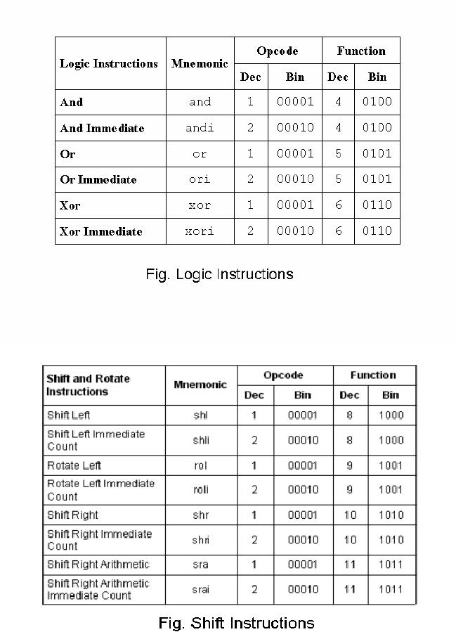
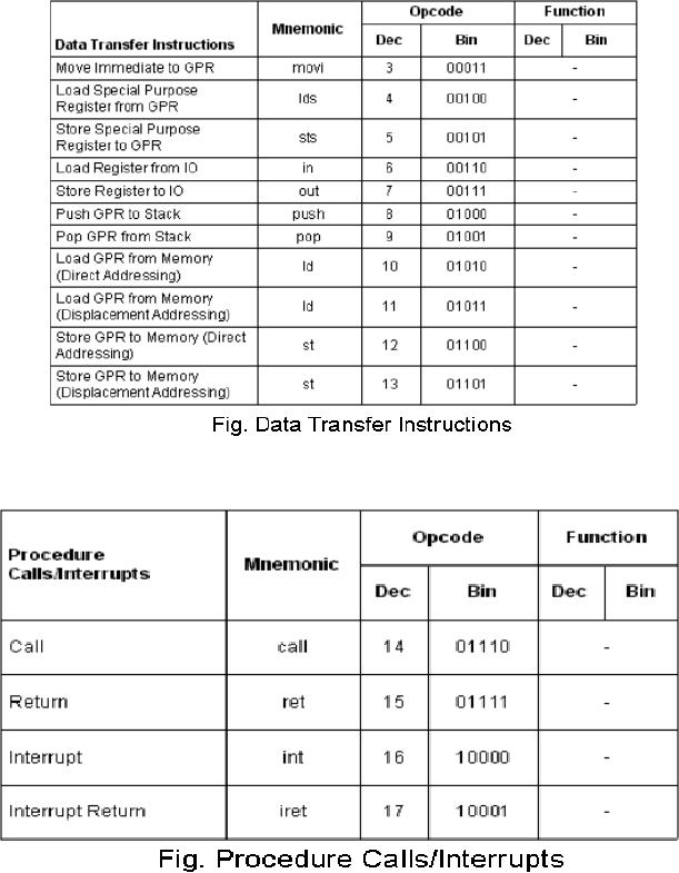
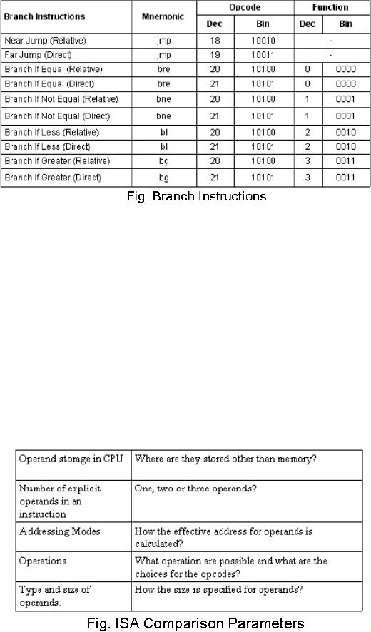
Falcon-E
Instruction
Summary
The
following are the tables
that list the instructions
that form the instruction
set of the
FALCON-E.
These instructions have been
grouped with respect to the
functionality they
provide.
Page
130
Last
Modified: 01-Nov-06
Advanced Computer
Architecture-CS501
Page
131
Last
Modified: 01-Nov-06
Advanced Computer
Architecture-CS501
Page
132
Last
Modified: 01-Nov-06
Advanced Computer
Architecture-CS501
Page
133
Last
Modified: 01-Nov-06
Advanced Computer
Architecture-CS501
Instruction
Set Architecture Comparison
In this
lecture, we compare the instruction
set architectures of the
various processors we
have
described/ designed up till now. These
processors are:
· EAGLE
· FALCON-A
· FALCON-E
· SRC
Classifying
Instruction Set
Architectures
In the
design of the ISA, the
choice of some of the parameters can
critically affect the
code
density (which is the number
of instructions required to complete a
given task),
cycles
per instruction (as some
instructions may take more
than one clock cycle, and
the
number of
cycles per instruction varies
from instruction to instruction,
architecture to
architecture),
and cycle time (the total
cycle time to execute a
given piece of code).
Classification
of different architectures is based on
the following parameters.
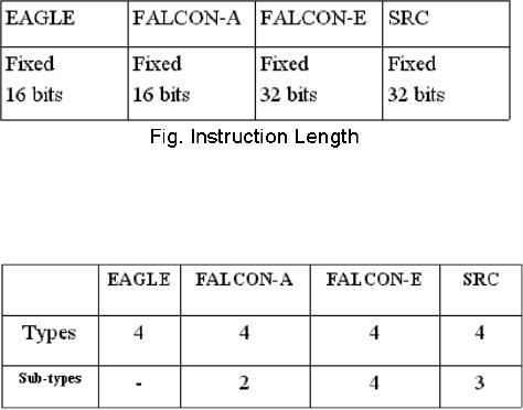
Instruction
Length
Page
134
Last
Modified: 01-Nov-06
Advanced Computer
Architecture-CS501
With
reference to the instruction
lengths in a particular ISA,
there are two decisions to
be
made;
whether the instruction will be
fixed in length or variable, and
what will be the
instruction
length or the range (in case
of variable instruction
lengths).
Fixed
versus variable
Fixed
instruction lengths are desirable
when simplicity of design is a goal. It
provides
ease of
implementation for assembling and
pipelining. However, fixed
instruction length
can be
wasteful in terms of code
density. All the RISC
machines use fixed
instruction
length
format
Instruction
Length
The
required instruction length
mainly depends on the number
of instruction required to
be in the
instruction set of a processor
(the greater the number of
instructions supported,
the
more bits are required to
encode the operation code),
the size of the register
file
(greater
the number of registers in the
register file, more is the
number of bits required
to
encode
these in an instruction), the
number of operands supported in
instructions (as
obviously,
it will require more bits to
encode a greater number of operands in
an
instruction),
the size of immediate operand field
(the greater the size, the
more the range
of values
that can be specified by the
immediate operand) and finally,
the code density
(which
implies how many
instructions can be encoded in a given
number of bits).
A summary
of the instruction lengths of
our processors is given in
the table below.
Instruction
types and sub-types
The
given table summarizes the
number of instruction types and
sub-types of the
processors
we have studied. We have
already studied these
instruction types, and
their
sub-types
in detail in the related
sections.
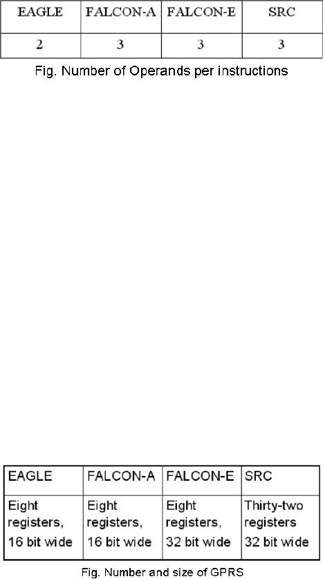
Number
of operands in the instructions
The
number of operands that may
be required in an instruction depends on
the type of
operation
to be performed by that instruction;
some instruction may have no
operands,
other
may have up to 3. But a
limit on the maximum number
of operands for the
instruction
set of a processor needs to be
defined explicitly, as it affects
the instruction
Page
135
Last
Modified: 01-Nov-06
Advanced Computer
Architecture-CS501
length
and code density. The
maximum number of operands
supported by the
instruction
set of
each processor under study
is given in the given table.
So FALCON-A, FALCON-
E and the
SRC processors may have 3, 2, 1 or no
operands, depending on the
instruction.
EAGLE
has a maximum number of 2 operands; it
may have one operand or no
operands
in an
instruction.
Explicit
operand specification in an instruction
gives flexibility in storage.
Implicit
operands
like an accumulator or a stack reduces
the instruction size, as
they need not be
coded
into the instruction.
Instructions of the processor
EAGLE have implicit
operands,
and we saw
that the result is
automatically stored in the accumulator,
without the
accumulator
being specified as a destination operand
in the instruction.
Number
and Size of General Purpose
Registers
While
designing a processor, another decision
that has to be made is about
the number of
registers present in
the register file, and the
size of the registers.
Increasing
the number of registers in the
register file of the CPU
will decrease the
memory
traffic, which is a desirable attribute,
as memory accesses take relatively
much
longer
time than register access.
Memory traffic decreases as
the number of registers is
increased, as
variables are copied into
the registers and these do not
have to be accessed
from
memory over and over again.
If there is a small number of registers,
the values
stored
previously will have to be saved back to
memory to bring in the new
values; more
registers will
solve the problem of
swapping in, swapping out.
However, a very large
register
file is not feasible, as it will
require more bits of the
instruction to encode
these
registers.
The size of the registers affects
the range of values that can be stored in
the
registers.
The
number of registers in the register
file, along with the size of
the registers, for each
of
the
processors under study, is in
the given table.
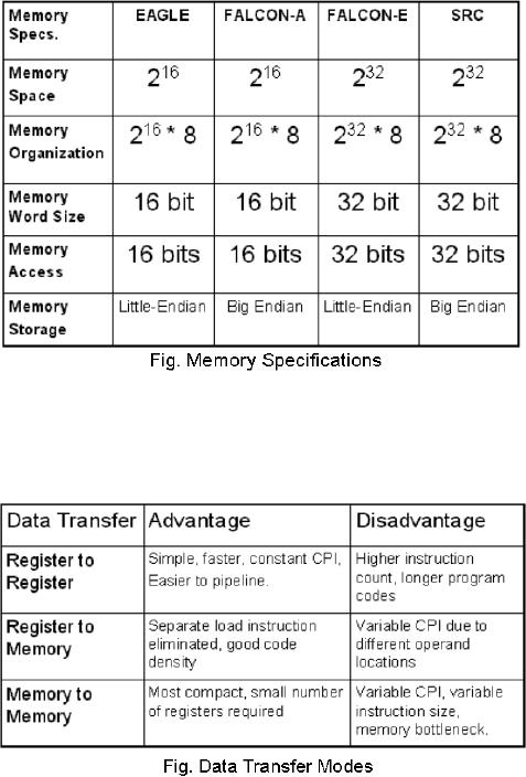
Memory
specifications
Memory
design is an integral part of the
processor design. We need to decide on
the
memory
space that will be available to
the processor, how the
memory will be organized,
memory
word size, memory access bus
width, and the storage
format used to store
words
in
memory. The memory
specifications for the
processor under comparison
are:
Page
136
Last
Modified: 01-Nov-06
Advanced Computer
Architecture-CS501
Data
transfer instructions
Data
needs to be transferred between
storage devices for processing. Data
transfers may
include
loading, storing back or copying of
the data. The different
ways in which data
transfers
may take place have their
related advantages and disadvantages. These
are listed
in the
given table.
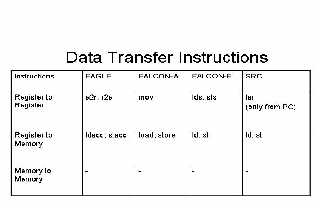
Following
are the data transfer
instructions included in the
instruction sets of
our
processors.
Register to
register transfers
As we can
see from the given
table on the next page, in
the processor EAGLE,
register to
register
transfers are of two types
only: register to accumulator, or
accumulator to
register.
Accumulator is a special-purpose
register.
FALCON-A
has a mov
instruction,
which can be used to move
data of any register to
any
other
register. FALCON-E has the
instructions `lds' and `sts'
which are used to
load/store
a
register from/to memory
after effective address
calculation.
SRC does
not provide any instruction
for data movement between
general-purpose
registers.
However, this can be accomplished
indirectly, by adopting either of
the
following
two approaches:
Page
137
Last
Modified: 01-Nov-06
Advanced Computer
Architecture-CS501
·
A
register's contents can be loaded into
another register via memory.
First storing
the
content of a register to a particular
memory location, and then
reading the
contents
of the memory from that
location into the register
we want to copy the
value to
can achieve this. However,
this method is very
inefficient, as it requires
memory
accesses, which are
inherently slow
operations.
·
A better
method is to use the addi
instruction with the
constant set to 0.
Register to
memory
EAGLE
has instructions to load
values from memory to the
special purpose register,
names
the accumulator, as well as
saving values from the
accumulator to memory.
Other
register
to memory transfers is not possible in
the EAGLE processor.
FALCON-A,
FALOCN-E
and the SRC have simple
load, store instructions and all
register-memory
transfers
are supported.
Memory
to memory
In any of
the processors under study,
memory-to-memory transfers are
not supported.
However,
in other processors, these
may be a possibility.
Control
Flow Instructions
All
processors have instructions to
control the flow of programs
in execution. The
general
control
flow instructions available in
most processors are:
· Branches
(conditional)
· Jumps
(unconditional)
· Calls
(procedure calls)
· Returns
(procedure returns)
Conditional
Branches
Whereas
jumps, calls and call
returns changes the control
flow in a specific
order,
branches
depend on some conditions; if
the conditions are met,
the branch may be
taken,
Page
138
Last
Modified: 01-Nov-06
Advanced Computer
Architecture-CS501
otherwise
the program flow may
continue linearly. The
branch conditions may
be
specified
by any of the following
methods:
· Condition
codes
· Condition
register
· Comparison
and branching
Condition
codes
The ALU
may contain some special
bits (also called flags),
which may have been
set (or
raised)
under some special circumstances.
For instance, a flag may be
raised if there is an
overflow
in the addition results of
two register values, or if a
number is negative. An
instruction
can then be ordered in the program
that may change the flow
depending on
any of
these flag's values. The
EAGLE processor uses these
condition codes for
branch
condition
evaluation.
Condition
register
A special
register is required to act as a branch
register, and any other
arbitrary register
(that is
specified in the branch
instruction), is compared against that
register, and the
branching
decision is based on the
comparison result of these
two registers. None of
the
processors
under our study use
this mode of conditional
branching.
Compare
and branch
In this
mode of conditional branching, comparison
is made part of the
branching
instruction.
Therefore, it is somewhat more
complex than the other
two modes. All the
processors
we are studying use this
mode of conditional branching.
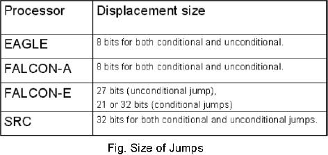
Size
of jumps
Jumps are
deviations from the linear
program flow by a specified
constant. All our
processors,
except the SRC, support
PC-relative jumps. The
displacement (or the
jump)
relative
to the PC is specified by the
constant field in the
instruction. If the constant
field
is wider
(i.e. there are more
bits reserved for the
constant field in the
instruction), the
jump can
be of a larger magnitude. Shown
table specifies the displacement size
for
various
processors.
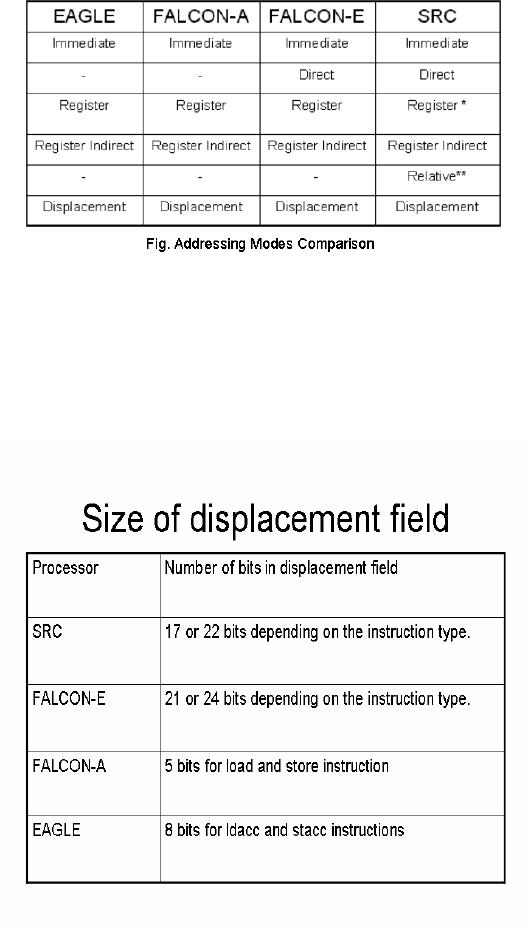
Addressing
Modes
All
processors support a variety of
addressing modes. An addressing mode is
the method
by which
architectures specify the
address of an object they will
access. The object
may
be a
constant, a register or a location in
memory.
Common
addressing modes are
Page
139
Last
Modified: 01-Nov-06
Advanced Computer
Architecture-CS501
·
Immediate
An
immediate field may be
provided in instructions, and a constant
value may be
given in
this immediate field, e.g.
123
is an
immediate value.
·
Register
A
register may contain the
value we refer to in an instruction,
for instance,
register
R4
may
contain the value being
referred to.
·
Direct
By direct
addressing mode, we mean the constant
field may specify the
location
of the
memory we want to refer to.
For instance, [123]
will
directly refer to the
memory
location 123's
contents.
·
Register
Indirect
A
register may contain the
address of memory location to
which we want to
refer
to,
for example, M
[R3].
·
Displacement
In this
addressing mode, the
constant value specified by
the immediate field
is
added to
the register value, and the
resultant is the index of
memory location that
is
referred to, e.g. M
[R3+123]
·
Relative
Relative
addressing mode implies PC-relative
addressing, for example, [PC+123]
will
refer to the memory location
that is 123 words farther
than the memory
index
currently
stored in the program
counter.
·
Indexed
or scaled
The
values contained in two registers
are added and the resultant
value is the
index to
the memory location we refer
to, in the indexed
addressing mode. For
example,
M
[[R1]+[R2]]. In the
scaled addressing mode, a register
value may be
scaled as
it is added to the value of
the other register to obtain
the index of
memory
location to be referred
to.
·
Auto
increment/ decrement
In the
auto increment mode, the
value held in a register is
used as the index to
memory
location that holds the
value of operand. After the
operand's value is
retrieved,
the register value is
automatically increased by 1 (or by
any specified
constant).
e.g. M
[R4]+, or M
[R4]+d. In the
auto decrement mode, the
register
value is
first decremented and then used as a
reference to the memory
location
that
referred to in the instruction, e.g.
-M
[R4].
As may be
obvious to the reader, some of
these addressing modes are
quite simple, others
are
relatively complex. The
complex addressing modes
(such as the indexed) reduce
the
instruction
count (thus improving code
density), at the cost of more
complex
implementation.
The
given table lists the
addressing modes supported by
the processors we are
studying.
Note
that the register-addressing mode is a special
case of the relative
addressing mode,
with
the constant equal to 0, and
only the PC can be used as a source.
Also note that, in
the
shown table, relative
implies PC-relative.
Page
140
Last
Modified: 01-Nov-06
Advanced Computer
Architecture-CS501
Displacement
addressing mode
We have
already talked about the
displacement-addressing mode. We look at
this
addressing
mode at length now.
The
displacement-addressing mode is the most
common of the addressing mode
used in
general
purpose processors. Some other
modes such as the indexed
based plus index,
scaled
and register indirect are
all slightly modified forms
of the displacement-addressing
mode.
The size of displacement plays a
key role in efficient
address calculation.
The
following
table specifies the size of the
displacement field in different
processors under
study.
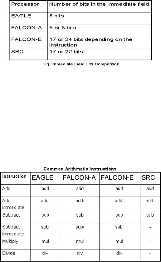
The
given table lists the size
of the immediate field in
our processors.
Page
141
Last
Modified: 01-Nov-06
Advanced Computer
Architecture-CS501
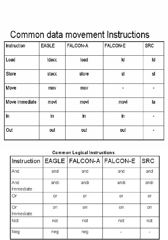
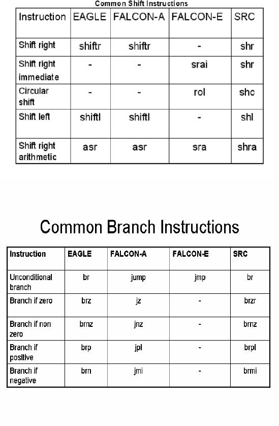
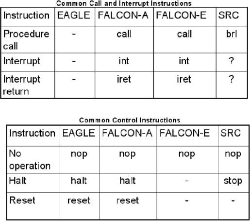
Instructions
common to all Instruction
Set Architectures
In this
section we have listed the
instructions that are common
to the Instruction
Set
Architectures
of all the processors under
our study.
· Arithmetic
Instructions
add, addi
& sub.
· Logic
Instructions
and,
andi, or, ori,
not.
· Shift
Instructions.
Right
shift, left shift &
arithmetic right
shift.
· Data
movement Instructions.
Load and
store instructions.
· Control
Instructions
Conditional
and unconditional branches, nop &
reset.
The
following tables list the
assembly language instruction
codes of these common
instructions
for all the processors
under comparison.
Page
142
Last
Modified: 01-Nov-06
Advanced Computer
Architecture-CS501
Page
143
Last
Modified: 01-Nov-06
Advanced Computer
Architecture-CS501
Page
144
Last
Modified: 01-Nov-06
Advanced Computer
Architecture-CS501
Instructions
unique to each processor
Now we
take a look at the instructions
that are unique to each of
the processors we are
studying.
EAGLE
The
EAGLE processor has a
minimal instruction set.
Following are the
instructions that
are
unique only to the EAGLE
processor. Note that these
instructions are unique
only
with
reference to the processor
set under our study;
some other processors may
have
these
instructions.
· movia
This
instruction is for moving
the immediate value to the
accumulator (the special
purpose
register)
· a2r
This
instruction is for moving
the contents of the
accumulator to a register
· r2a
For
moving register contents to
the accumulator
· cla
For
clearing (setting to zero)
the value in the
accumulator
FALCON-A
There is
only one instruction unique to
the FALCON-A processor;
· ret
This
instruction is used to return
control to a calling procedure.
The calling
procedure
may save the PC value in a
register ra, and when this
instruction is
called,
the PC value is restored. In RTL, we
write this as
PC R
[ra];
Page
145
Last
Modified: 01-Nov-06
Advanced Computer
Architecture-CS501
FALCON-E
The
instructions unique to the
FALCON-E processor are
listed:
· push
To push
the contents of a specified
general purpose register to the
stack
· pop
To pop
the value that is at the
top of the stack
· ldr
To load a
register with memory
contents using displacement
addressing mode
· str
To store a
register value into memory,
using displacement addressing mode
· bl
To branch
if source operand is less than target
address
· bg
To branch
if source operand is greater than target
address
· muli
To
multiply an immediate value
with a value stored in a
register
· divi
To divide
a register value by the
immediate value
·
xor,
xori
To
evaluate logical `exclusive
or'
· ror,
rori
SRC
Following
are the instructions that
are unique to the SRC processor,
among of the
processors
under study
· ldr
To load
register from memory using
PC-relative address
· lar
To load a
register with a word from
memory using relative
address
· str
To store
register value to memory
using relative
address
· brlnv
This
instruction is to tell the
processor to `never branch' at
that point in
program.
The
instruction saves the
program counter's contents to
the register
specified
· brlpl
This
instruction instructs the
processor to branch to the
location specified by a
register
given in the instruction, if
the condition register's
value is positive.
Return
address is saved before
branching.
· brlmi
This
instruction instructs the
processor to branch to the
location specified by a
register
given in the instruction, if
the condition register's
value is negative.
Return
address is saved before
branching.
· brlzr
This
instruction instructs the
processor to branch to the
location specified by a
register
given in the instruction, if
the condition register's
value equals zero.
Return
address is saved before
branching.
Page
146
Last
Modified: 01-Nov-06
Advanced Computer
Architecture-CS501
·
brlnz
This
instruction instructs the
processor to branch to the
location specified by a
register
given in the instruction, if
the condition register's
value does not
equal
zero.
Return address is saved
before branching.
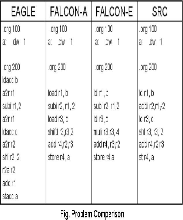
Problem
Comparison
Given is
the code for a simple C
statement:
a=(b-2)+4c
The
given table gives its
implementation in all the
four processors under
comparison.
Note
that this table highlights
the code density for
each of the processors;
EAGLE, which
has
relatively fewer specialized
instructions, and so it takes more
instructions to carry
out
this
operation as compared with the rest of
the processors.
Page
147
Last
Modified: 01-Nov-06
Advanced Computer
Architecture-CS501
Page
148
Last
Modified: 01-Nov-06
Table of Contents:
- Computer Architecture, Organization and Design
- Foundations of Computer Architecture, RISC and CISC
- Measures of Performance SRC Features and Instruction Formats
- ISA, Instruction Formats, Coding and Hand Assembly
- Reverse Assembly, SRC in the form of RTL
- RTL to Describe the SRC, Register Transfer using Digital Logic Circuits
- Thinking Process for ISA Design
- Introduction to the ISA of the FALCON-A and Examples
- Behavioral Register Transfer Language for FALCON-A, The EAGLE
- The FALCON-E, Instruction Set Architecture Comparison
- CISC microprocessor:The Motorola MC68000, RISC Architecture:The SPARC
- Design Process, Uni-Bus implementation for the SRC, Structural RTL for the SRC instructions
- Structural RTL Description of the SRC and FALCON-A
- External FALCON-A CPU Interface
- Logic Design for the Uni-bus SRC, Control Signals Generation in SRC
- Control Unit, 2-Bus Implementation of the SRC Data Path
- 3-bus implementation for the SRC, Machine Exceptions, Reset
- SRC Exception Processing Mechanism, Pipelining, Pipeline Design
- Adapting SRC instructions for Pipelined, Control Signals
- SRC, RTL, Data Dependence Distance, Forwarding, Compiler Solution to Hazards
- Data Forwarding Hardware, Superscalar, VLIW Architecture
- Microprogramming, General Microcoded Controller, Horizontal and Vertical Schemes
- I/O Subsystems, Components, Memory Mapped vs Isolated, Serial and Parallel Transfers
- Designing Parallel Input Output Ports, SAD, NUXI, Address Decoder , Delay Interval
- Designing a Parallel Input Port, Memory Mapped Input Output Ports, wrap around, Data Bus Multiplexing
- Programmed Input Output for FALCON-A and SRC
- Programmed Input Output Driver for SRC, Input Output
- Comparison of Interrupt driven Input Output and Polling
- Preparing source files for FALSIM, FALCON-A assembly language techniques
- Nested Interrupts, Interrupt Mask, DMA
- Direct Memory Access - DMA
- Semiconductor Memory vs Hard Disk, Mechanical Delays and Flash Memory
- Hard Drive Technologies
- Arithmetic Logic Shift Unit - ALSU, Radix Conversion, Fixed Point Numbers
- Overflow, Implementations of the adder, Unsigned and Signed Multiplication
- NxN Crossbar Design for Barrel Rotator, IEEE Floating-Point, Addition, Subtraction, Multiplication, Division
- CPU to Memory Interface, Static RAM, One two Dimensional Memory Cells, Matrix and Tree Decoders
- Memory Modules, Read Only Memory, ROM, Cache
- Cache Organization and Functions, Cache Controller Logic, Cache Strategies
- Virtual Memory Organization
- DRAM, Pipelining, Pre-charging and Parallelism, Hit Rate and Miss Rate, Access Time, Cache
- Performance of I/O Subsystems, Server Utilization, Asynchronous I/O and operating system
- Difference between distributed computing and computer networks
- Physical Media, Shared Medium, Switched Medium, Network Topologies, Seven-layer OSI Model