 |
Behavioral Register Transfer Language for FALCON-A, The EAGLE |
| << Introduction to the ISA of the FALCON-A and Examples |
| The FALCON-E, Instruction Set Architecture Comparison >> |
Advanced Computer
Architecture-CS501
Advanced
Computer Architecture
Lecture
No. 9
Reading
Material
Handouts
Slides
Summary
4) Use of
Behavioral Register Transfer
Language (RTL) to describe
the
FALCON-A
5) The
EAGLE
6) The
Modified EAGLE
Use
of Behavioral Register Transfer
Language (RTL) to describe
the
FALCON-A
The
use of RTL (an acronym for
the Register Transfer
Language) to describe
the
FALCON-A
is discussed in this section.
FALCON-A is the sample machine we
are
building
in order to enhance our understanding of
processors and their
architecture.
Behavior
vs. Structure
Computer
design involves various levels of
abstraction. The behavioral
description of a
machine
is a higher level of abstraction, as
compared with the structural
description. Top-
down
approach is adopted in computer design.
Designing a computer typically starts
with
defining
the behavior of the overall
system. This is then broken
down into the behavior
of
the
different modules. The
process continues, till we
are able to define, design and
implement
the structure of the
individual modules.
As
mentioned earlier, we are interested in
the behavioral description of
our machine, the
FALCON-A,
in this section.
Register
Transfer Language
The RTL
is a formal way of expressing
the behavior and structure of a
computer.
Behavioral
RTL
Behavioral
Register Transfer Language is
used to describe what a
machine does, i.e. it
is
used to
define the functionality the
machine provides. Basically,
the behavioral
architecture
describes the algorithms
used in a machine, written as a
set of process
statements. These
statements may be sequential statements or
concurrent statements,
including
signal assignment statements and wait
statements.
Structural
RTL
Structural
RTL is used to describe the
hardware implementation of the
machine. The
structural
architecture of a machine is the
logic circuit implementation
(components and
their
interconnections), that facilitates a
certain behavior (and hence
functionality) for
that
machine.
Using
RTL to describe the static properties of the
FALCON-A
We can
employ the RTL for the
description of various properties of
the FALCON-A that
we have
already discussed.
Page
104
Last
Modified: 01-Nov-06
Advanced Computer
Architecture-CS501
Specifying
Registers
In RTL,
we will refer to a register by its
abbreviated, alphanumeric name,
followed by
the
number of bits in the
register enclosed in angle brackets `< >'.
For instance, the
instruction
register (IR), of 16 bits
(numbered 0 to 15), will be referred to
as,
IR<15..0>
Naming
of the Fields in a Register
We can name
the different fields of a
register using the :=
notation. For example, to
name
the
most significant bits of the
instruction register as the
operation code (or simply
op),
we may
write:
op<4..0>
:= IR<15..11>
Note
that using this notation to
name registers or register fields will
not create a new
copy
of the
data or the register fields;
it is simply an alias for an already
existing register, or
part of a
register.
Fields in the
FALCON-A Instructions
We now
use the RTL naming operator
to name the various fields of
the RTL instructions.
Naming
the fields appropriately
helps us make the study of
the behavior of a
processor
more
readable.
op<4..0>:=
IR<15..11>:
operation
code field
ra<2..0>
:= IR<10..8>:
target
register field
rb<2..0>
:= IR<7..5>:
operand or
address index
rc<2..0>
:= IR<4..2>:
second
operand
c1<4..0>
:= IR<4..0>:
short
displacement field
c2<7..0>
:= IR<7..0>:
long
displacement or the immediate
field
We are
already familiar with these
fields, and their usage in
the various
instruction
formats
of the RTL.
Describing the
Processor State using RTL
The
processor state defines the
contents of all the register
internal to the CPU at a
given
time.
Maintaining or restoring the
machine or processor state is
important to many
operations,
especially procedure calls and
interrupts; the processor
state needs to be
restored
after a procedure call or an
interrupt so normal operation can
continue.
Our
processor state consists of the
following:
PC<15..0>:
program
counter (the PC holds the memory
address of the next
instruction)
IR<15..0>:
instruction
register (used to hold the current
instruction)
Run:
one
bit run/halt
indicator
Strt:
start
signal
R
[0..7]<15..0>: 8 general purpose
registers, each consisting of 16
bits
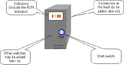
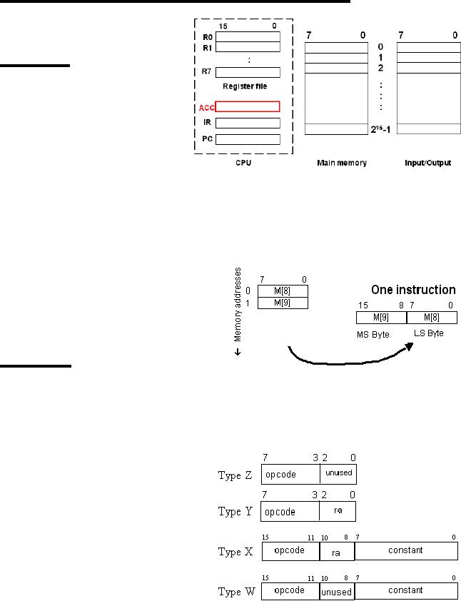
FALCON-A
in a black
box
The
given figure shows
what a
processor appears as
to a
user. We see a start
button
that is basically
used
to start
up the processor,
and a run
indicator that
turns on
when the processor
is in the
running state.
Page
105
Last
Modified: 01-Nov-06
Advanced Computer
Architecture-CS501
There
may be several other
indicators as well. The
start button as well as the
run indicator
can be observed on
many machines.
Using
RTL to describe the dynamic properties of
the FALCON-A
We have
just described some of the
static properties of the FALCON-A.
The RTL can
also be
employed to describe the
dynamic behavior of the
processor in terms of
instruction
interpretation and execution.
Conditional
expressions can be specified using the
RTL. For instance, we may
specify a
conditional
subtraction operation employing RTL
as
(op=2) :
R[ra] ← R[rb] -
R[rc];
This
instruction means that "if"
the operation code of the
instruction equals 2 (00010 in
binary),
then subtract the value
stored in register rc from that of
register rb, and store
the
resulting
value in register ra.
Effective
address calculations in RTL (performed at
runtime)
The
operand or the destination address
may not be specified
directly in an instruction,
and it
may be required to compute
the effective address at
run-time. Displacement and
relative
addressing modes are instances of
such situations. RTL can be used to
describe
these
effective address
calculations.
Displacement
address
A
displacement address is calculated, as
shown:
disp<15..0>
:= (R[rb]+ (11α c1<4>)
c1<4..0>);
This
means that the address is
being calculated by adding
the constant value specified
by
the
field c1 (which is first
sign extended), to the value
specified by the register
rb.
Relative
address
A
relative address is calculated by
adding the displacement to
the contents of the
program
counter
register (that holds the
instruction to be executed next in a
program flow). The
constant
is first sign-extended. In RTL this is
represented as,
rel<15..0>:=PC+(8αc2<7>)©c2<7..0>;
Range of
memory addresses
Using
the displacement or the
relative addressing modes,
there is a specific range of
memory
addresses that can be
accessed.
· Range of
addresses when using direct
addressing mode (displacement with
rb=0)
o If
c1<4>=0 (positive displacement)
absolute addresses range: 00000b
to
01111b (0 to
+15)
o If
c1<4>=1 (negative displacement)
absolute addresses range: 11111b
to
10000b
(-1 to -16)
· Address range in
case of relative
addressing
o The
largest positive value that
can be specified using 8 bits
(since we have
only 8
bits available in c2<7..0>), is
27-1, and the
most negative value
that
can be represented
using the same is 27. Therefore, the range of
addresses
or
locations that can be referred to
using this addressing mode is
127
locations
forward or 128 locations backward
from the Program
Counter
(PC).
Instruction
Fetch Operation (using
RTL)
Page
106
Last
Modified: 01-Nov-06

Advanced Computer
Architecture-CS501
We will
now employ the notation
that we have learnt to
understand the
fetch-execute
cycle of
the FALCON-A processor.
The RTL
notation for the instruction
fetch process is
instruction_Fetch
:= (
!Run&Strt :
Run ← 1,
Run : (IR
← M[PC], PC
← PC +
2;
instruction_Execution)
);
This is how the
instruction-fetch phase of the
fetch-execute
cycle
for FALCON-A can be represented
using RTL. Recall
that
":=' is the naming operator,
"!" implies a logical NOT,
"&"
implies a
logical AND, "←" represents a
transfer operation,
";"
is used to
separate sequential statements, and
concurrent
statements
are separated by ",". We can
observe that in the
instruction_Fetch
phase, if the machine is not in the
running
state and the
start bit has been set, then the run
bit is also
set to
true. Concurrently, an instruction is
fetched from the
instruction
memory; the program counter
(PC) holds the next
instruction
address, so it is used to refer to the
memory
location
from where the instruction is to be
fetched.
Simultaneously,
the PC is incremented by 2 so it will
point to
the next
instruction. (Recall that
our instruction word is
2
bytes
long, and the instruction memory is
organized into 1-
byte
cells). The next step is the instruction
execution phase.
Difference
between "," and ";" in RTL
We again
highlight the difference
between the "," and ";". Statements
separated by a ","
take place
during the same clock
pulse. In other words, the
order of execution of
statements
separated by ","
does
not matter.
On the
other hand, statements separated by a
";"
take
place on successive clock pulses.
In
other
words, if statements are separated by
";"
the one
on the left must complete
before
the one
on the right starts. However,
some things written with one
RTL statement can
take
several clocks to
complete.
We return
to our discussion of the
instruction-fetch phase. The
statement
!Run&Strt : Run
← 1
is
executed when `Run' is 0, and
`Strt' is 1, that is, Strt
has been set. It is used to
set the
Run
bit. No action takes place
when both `Run' and `Strt'
are 0.
The
following two concurrent
register transfers are
performed when `Run' is set
to 1, (as
`:' is a
conditional operator; if the
condition is met, the
specified action is
taken).
Page
107
Last
Modified: 01-Nov-06
Advanced Computer
Architecture-CS501
IR ← M[PC]
PC ← PC + 2
Since
these instructions appear
concurrent, and one of the instructions
is using the value
of PC
that the other instruction
is updating, a question arises;
which of the two values
of
the PC is
used in the memory access?
As a rule, all right hand
sides of the register
transfers
are evaluated before the
left hand side is
evaluated/updated. In case of
simultaneous
register transfers (separated by a
","), all the right
hand side expressions
are
evaluated
in the same clock-cycle,
before they are assigned.
Therefore, the old,
un-
incremented
value of the PC is used in
the memory access, and the
incremented value is
assigned
to the PC afterwards. This corresponds to
"master-slave" flip-flop operation
in
logic
circuits.
This
makes the PC point to the
next instruction in the
instruction memory. Once
the
instruction
has been fetched, the
instruction execution starts. We can also
use i.F for
instruction_Fetch
and i.E for instruction_Execution.
This will make the Fetch
operation
easy to
write.
iF := ( !Run&Strt
: Run ← 1, Run :
(IR ← M[PC], PC
← PC +
2;
iE )
);
Page
108
Last
Modified: 01-Nov-06
Advanced Computer
Architecture-CS501
Instruction
Execution (Describing the Execute
operation using
RTL)
Once an
instruction has been fetched
from the instruction memory,
and the program
counter
has been incremented to
point to the next
instruction in the memory,
instruction
execution
commences. In the instruction
fetch-execute cycle we showed in
the preceding
discussion,
the entire instruction
execution code was
aliased iE (or
instruction_Execution),
through the assignment operator
":=". Now we look at
the
instruction
execution in detail.
iE :=
(
(op<4..0>=
1) : R[ra] ← R[rb]+
(11α c1<4>)
c1<4..0>,
(op<4..0>=
2) : R[ra] ← R[rb]-R[rc],
...
...
(op<4..0>=31)
: Run ← 0,);
iF );
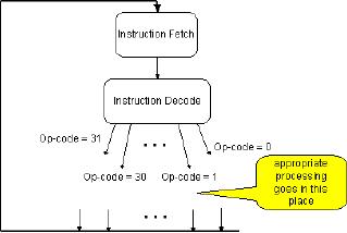
As we can
see, the instruction
execution can be described in RTL by
using a long list of
concurrent,
conditional operators that are
inherently `disjoint'. Being
inherently
disjointed
implies that at any
instance, only one of the
conditions can be met; hence one
of the
statements is executed. The long
list of statements is basically all of
the
instructions
that are a part of the
FALCON-A instruction set, and
the condition for
their
execution
is related to the operation
code of the instruction
fetched. We will take a closer
look at
the entire list in our
subsequent discussion. Notice that in
the instruction
execute
phase,
besides the long list of
concurrent,
disjoint
instructions, there is also
the
instruction
fetch or iF sequenced at
the
end.
This implies that once one of
the
instructions
from the list is executed,
the
instruction
fetch is called to fetch the
next
instruction.
As shown before,
the
instruction
fetch will call the
instruction
execute
after fetching a certain
instruction,
hence the
instruction fetch-execute
cycle
continues.
The
instruction fetch-execute cycle is
shown schematically in the above
given figure.
We now
see how the various
instructions in the execute
code of the fetch-execute
cycle
of
FALCON-A, are represented
using the RTL. These
instructions form the
instruction
set of
the FALCON-A.
jump
instructions
Some of
the instructions listed for
the instruction execution
phase are jump instruction,
as
shown.
(Note `. . .' implies that
more instructions may
precede or follow, depending
on
whether
it is placed before the instructions
shown, or after).
iE :=
(
. . .
. . .
If op-code is
20, the branch is taken
unconditionally (the jump
instruction).
(op<4..0>=20)
: (cond
:
PC
← R[ra]+C2(sign
extended)),
If the
op-code is 16, the condition
for branching is checked, and if the
condition is being
met,
the branch is taken;
otherwise it remains untaken, and
normal program flow
will
continue.
Page
109
Last
Modified: 01-Nov-06
Advanced Computer
Architecture-CS501
(op<4..0>=
16) : cond : (PC ← PC+C2
(sign extended ))
. . .
. . .
Arithmetic
and Logical Instructions
Several
instructions provide arithmetic and
logical operations functionality.
Amongst the
list of
concurrent instructions of the iE
phase, the instructions
belonging to this
category
are
highlighted:
iE :=
(
. . .
. . .
If op-code is 0,
the instruction is `add'.
The values in register rb and rc
are added and the
result is
stored in register rc
(op<4..0>=0)
: R[ra] ← R[rb]
+ R[rc],
Similarly,
if op-code is 1, the instruction is addi;
the immediate constant
specified by the
constant
field C1 is sign extended and
added to the value in
register rb. The result
is
stored in
the register ra.
(op<4..0>=1)
: R[ra] ←R[rb]
+ (11α C1<4>)
C1<4..0>,
For
op-code 2, value stored in register rc is
subtracted from the value
stored in register rb,
and the
result is stored in register
ra.
(op<4..0>=2)
: R[ra] ← R[rb]
- R[rc],
If op-code is 3,
the immediate constant C1 is
sign-extended, and subtracted from
the
value
stored in rb. Result is stored in
ra.
(op<4..0>=3)
: R[ra] ← R[rb]-
(11α C1<4>)
C1<4..0>,
For
op-code 4, values of rb and rc register
are multiplied and result is stored in
the
destination
register.
(op<4..0>=4)
: R[ra] ← R[rb]
* R[rc],
If the
op-code is 5, contents of register rb are
divided by the value stored in
rc, result is
concatenated
with 0s, and stored in ra.
The remainder is stored in
R0.
(op<4..0>=5)
: R[ra] ← R[0]
©R[rb]/R[rc],
R[0]
← R[0]
©R[rb]%R[rc],
If op-code equals 8,
bit-wise logical AND of rb and rc
register contents is assigned to
ra.
(op<4..0>=8)
: R[ra] ← R[rb]
& R[rc],
If op-code equals 8,
bit-wise logical OR of rb and rc register
contents is assigned to ra.
(op<4..0>=10)
: R[ra] ← R[rb]
~ R[c],
For
op-code 14, the contents of
register specified by field rc
are inverted (logical NOT
is
taken),
and the resulting value is stored in
register ra.
(op<4..0>=14)
: R[ra] ← !
R[rc],
. . .
. . .
Shift
Instructions
The
shift instructions are also a
part of the instruction set
for FALCON-A, and these
are
listed in
the instruction execute
phase in the RTL as
shown.
iE :=
(
. . .
. . .
Page
110
Last
Modified: 01-Nov-06
Advanced Computer
Architecture-CS501
If the
op-code is 12, the contents of
the register rb are shifted
right N bits. N is
the
number
specified in the constant
field. The space that
has been created due to the
shift out
of bits
is filled with 0s through
concatenation. In RTL, this is
shown as:
(op<4..0>=12)
: R[ra]<15..0> ← R
[rb]<(15-N)..0>©(Nα0),
If op-code is
13, rb value is shifted
left, and 0s are inserted in place of
shifted out
contents
at the right side of the
value. The result is stored in
ra.
(op<4..0>=13)
: R[ra]<15..0> ← (Nα0)©R
[rb]<(15)..N>,
For
op-code 15, arithmetic shift
right operation is carried
out on the value stored in
rb.
The
arithmetic shift right
shifts a signed binary number stored in
the source register to
the
right,
while leaving the sign-bit
unchanged. Note that α means
replication, and means
concatenation.
(op<4..0>=15)
: R[ra]<15..0> ← Nα(R
[rb]<15>)(R
[rb]<15..N>),
. . .
. . .
Data
transfer instructions
Several
of the instructions belong to
the data transfer
category.
iE :=
(
. . .
. . .
Op-code
29 specifies the load instruction,
i.e. a memory location is
referenced and the
value
stored in the memory location is copied
to the destination register.
The effective
address
of the memory location to be referenced
is calculated by sign extending
the
immediate
field, and adding it to the
value specified by register
rb.
(op<4..0>=29)
: R[ra]← M[R[rb]+
(11α C1<4>)
C1<4..0>],
A value
is stored back to memory from a register
using the op-code 28. The
effective
address
in memory where the value is
to be stored is calculated in a similar
fashion as the
load
instruction.
(op<4..0>=28)
: M[R[rb]+ (11α C1<4>)
C1<4..0>] ← R
[ra],
The
move instruction has the
op-code 6. The contents of one register
are copied to
another
register through this
instruction.
(op<4..0>=6)
: R[ra] ← R[rb],
To store an
immediate value (specified by
the field C2 of the
instruction) in a register,
the
op-code 7 is
employed. The constant is
first sign-extended.
(op<4..0>=7)
: R[ra] ← (8αC2<7>)©C2<7..0>,
If the
op-code is 24, an input is obtained
from a certain input device,
and the input word
is stored
into register ra. The
input device is selected by
specifying its address
through the
constant
C2.
(op<4..0>=24)
: R[ra] ← IO[C2],
Unconditional
branch (jump)If the
op-code is 25, an output (the
register ra value) is sent
to an
output device (where the
address of the output device
is specified by the
constant
C2).
(op<4..0>=25)
: IO[C2] ← R[ra],
. . .
. . .
Page
111
Last
Modified: 01-Nov-06
Advanced Computer
Architecture-CS501
Miscellaneous
instructions
Some
more instruction included in the FALCON-A
are
iE :=
(
. . .
. . .
The
no-operation (nop) instruction, if
the op-code is 21. This
instructs the processor to
do
nothing.
(op<4..0>=
21) :
,
If the
op-code is 31, setting the
run bit to 0 halts the
processor.
(op<4..0>=
31) : Run ← 0,
Halt the processor
(halt)
At the
end of this concurrent list of
instructions, there is an instruction
i.F (the instruction
fetch).
Hence when an instruction is
executed, the next
instruction is fetched, and
the
cycle
continues, unless the
processor is halted.
);
iF
);
Note:
For Assembler and Simulator Consult
Appendix.
The
EAGLE
(Original
version)
Another
processor that we are going
to study is the EAGLE. We
have developed two
versions
of it, an original version, and a
modified version that takes
care of the
limitations
in the
original version. The study
of multiple processors is going to
help us get
thoroughly
familiar with the processor
design, and the various possible designs
for the
processor.
However, note that these
machines are simplified
versions of what a
real
machine
might look like.
Introduction
The
EAGLE is an accumulator-based machine. It
is a simple processor that will
help us
in our
understanding of the processor design
process.
EAGLE is
characterized by the
following:
· Eight
General Purpose Registers of the
CPU. These are named R0,
R1...R7. Each
register
is 16-bits in length.
· Two
16-bit system registers transparent to
the programmer are the
Program
Counter
(PC) and the Instruction
Register (IR). (Being
transparent to the
programmer
implies the programmer may
not directly manipulate the
values to
these
registers. Their usage is the
same as in any other
processor)
· Memory
word size is 16 bits
· The
available memory space size is 216
bytes
· Memory
organization is 216 x 8 bits. This
means that there are 216
memory cells,
each one
byte long.
· Memory
is accessed in 16 bit words
(i.e., 2 byte chunks)
· Little-endian
byte storage is employed.
Page
112
Last
Modified: 01-Nov-06
Advanced Computer
Architecture-CS501
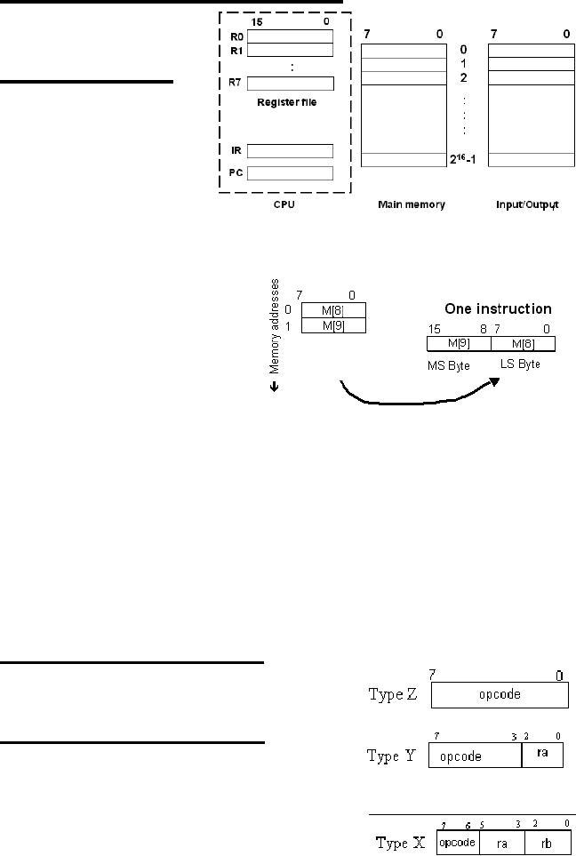
Programmer's
View of the EAGLE
The
programmer's view of
the
EAGLE
processor is shown by
means of
the given figure.
EAGLE:
Notation
Let us
take a look at the
notation
that will be employed
for
the study of the
EAGLE.
Enclosing
the register name in
square
brackets refers to
register
contents; for
instance,
R[3]
means contents of
register
R3.
Enclosing
the location address in
square brackets, preceded by `M', lets us
refer to
memory
contents. Hence M
[8] means contents of memory
location 8.
As little
endian storage is employed,
a
memory
word at
address x is defined
as the 16
bits at address x +1 and x.
For
instance, the bits at
memory
location
9,8 define the memory
word at
location
8. So employing the special
notation
for 16-bit memory words,
we
have
M
[8]<15...0>:=M [9]©M [8]
Where
is used to represent concatenation
EAGLE
Features
The
following features characterize
the EAGLE.
· Instruction
length is variable. Instructions
are either 8 bits or 16
long, i.e.,
instruction
size is either 8-bits or
16-bits.
· The
instructions may have either
one or two operands.
· The
only way to access memory is
through load and store
instructions.
· Limited
addressing modes are
supported
EAGLE:
Instruction Formats
There
are five instruction formats
for the EAGLE. These
are
Type Z
Instruction Format
The Z
format instructions are
half-word (1 byte)
instructions,
containing just the op-code
field of 8 bits,
as
shown
Type Y
Instruction Format
The
type Y instructions are also
half-word. There is
an op-code
field of 5 bits, and a register operand
field
ra.
Type
X Instruction Format
Type X
instructions are also half-word
instructions,
Page
113
Last
Modified: 01-Nov-06
Advanced Computer
Architecture-CS501
with a
2-bit op-code field, and two
3-bit operand register fields, as
shown.
Page
114
Last
Modified: 01-Nov-06
Advanced Computer
Architecture-CS501
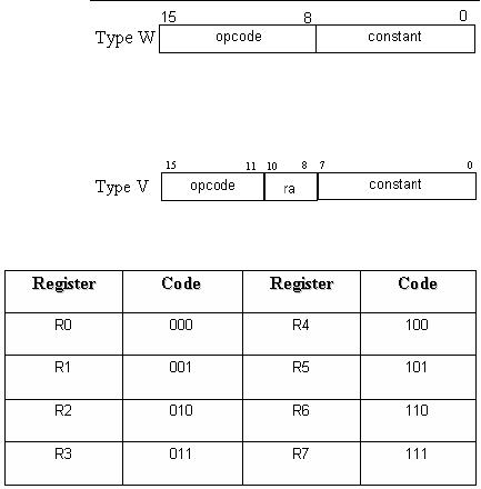
Type
W instruction format
The
instructions in this type
are 1-
word
(16-bit) in length. 8 bits
are
reserved
for the op-code, while the
remaining 8 bits form the
constant (immediate
value)
field.
Type
V instruction format
Type V
instructions are also
1-word
instructions,
containing an op-code
field of
5 bits, an operand register
field
of
3
bits,
and
8
bits
for
a
specifying
a
constant.
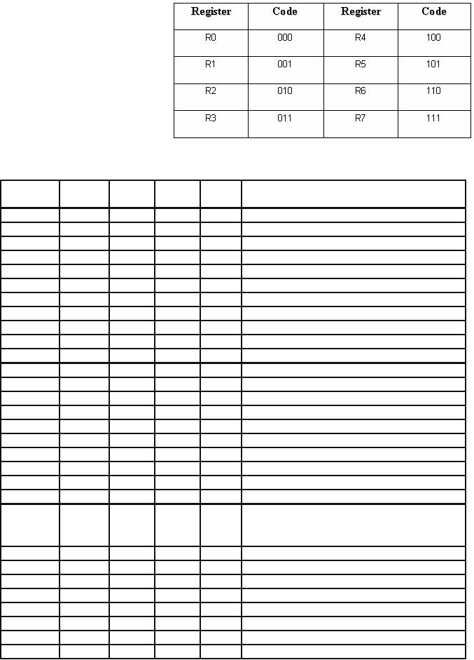
Encoding
of the General Purpose
Registers
The
encoding for the
eight
GPRs is
shown in the table.
These
binary codes are to
be used
in place of the
`place-holders'
ra, rb in the
actual
instructions of the
processor
EAGLE.
Listing
of
EAGLE
instructions
with respect to
instruction
formats
The
following is a brief introduction to
the various instructions of
the processor EAGLE,
categorized
with respect to the
instruction formats.
Type
Z
There
are four type Z
instructions,
· halt(op-code=250)
This
instruction halts the
processor
· nop(op-code=249)
nop, or
the no-operation instruction
stalls the processor for
the time of execution
of a
single instruction. It is useful in
pipelining.
· init(op-code=251)
This
instruction is used to initialize
all the registers, by setting
them to 0
· reset(op-code=248)
This
instruction is used to initialize
the processor to a known
state.In this
instruction
the control step counter is
set to zero so that the
operation begins at the
start of
the instruction fetch and
besides this PC is also set to a
known value so
that
machine operation begins at a known
instruction.
Type
Y
Seven
instructions of the processor
are of type Y. These
are
· add(op-code=11)
The
type Y add instruction adds
register ra's contents to
register R0. For
example,
add
r1
In
the
behavioral
RTL,
we
show
this
as
R[0]
← R[1]+R[0]
Page
115
Last
Modified: 01-Nov-06
Advanced Computer
Architecture-CS501
·
and(op-code=19)
This
instruction obtains the
logical AND of the value stored in
register specified
by field
ra and the register R0, and
assigns the result to R0, as
shown in the
example:
and
r5
which is
represented in RTL as
R[0]
← R[1]&R[0]
·
div(op-code=16)
This
instruction divides the
contents of register R0 by the
value stored in the
register
ra, and assigns result to
R0. The remainder is stored in
the divisor
register,
as shown in example,
div
r6
In RTL,
this is
R[0]
← R[0]/R[6]
R[6]
← R[0]%R[6]
·
mul
(op-code = 15)
This
instruction multiplies the
values stored in register R0 and the
operand
register,
and assigns the result to
R0). For example,
mul
r4
In RTL,
we specify this as
R[0]
← R[0]*R[4]
·
not
(op-code = 23)
The
not instruction inverts the
operand register's value and assigns it
back to the
same
register, as shown in the
example
not
r6
R[6]
← !
R[6]
·
or
(op-code=21)
The or
instruction obtains the
bit-wise OR of the operand register's and
R0's
value,
and assigns it back to R0. An
example,
or
r5
R[0]
← R[0] ~
R[5]
·
sub
(op-code=12)
The sub
instruction subtracts the
value of the operand register
from R0 value,
assigning
it back to register R0.
Example:
sub
r7
In
RTL:
R[0]
← R[0]
R[7]
Type
X
Only one
instruction falls under this
type. It is the `mov'
instruction that is useful
for
register
transfers
· mov
(op-code = 0)
The
contents of one register are copied to
the destination register
ra.
Example:
mov r5, r1
RTL
Notation: R[5]← R[1]
Page
116
Last
Modified: 01-Nov-06
Advanced Computer
Architecture-CS501
Type
W
Again,
only one instruction belongs to
this type. It is the branch
instruction
· br
(op-code = 252)
This is
the unconditional branch
instruction, and the branch
target is specified by
the
8-bit immediate field. The
branch is taken by incrementing
the PC with the
new
value. Hence it is a `near'
jump. For instance,
br
14
PC ← PC+14
Type
V
Most of
the instructions of the
processor EAGLE are of the
format type V. These
are
· addi
(op-code = 13)
The addi
instruction adds the
immediate value to the
register ra, by first
sign-
extending
the immediate value. The
result is also stored in the register
ra. For
example,
addi r4,
31
In
behavioral RTL, this
is
R[4]
←
R[4]+(8αc<7>)©c<7...0>;
· andi
(op-code = 20 )
Logical
`AND' of the immediate value and
register ra value is obtained
when this
instruction
is executed, and the result is
assigned back to register ra. An
example,
andi
r6, 1
R[6]
← R[6]
&1
· in
(op-code=29)
This
instruction is to read in a word
from an IO device at the
address specified by
the
immediate field, and store it in the
register ra. For
instance,
in r1,
45
In RTL
this is
R[1]
← IO[45]
· load
(op-code=8)
The
load instruction is to load
the memory word into
the register ra.
The
immediate
field specifies the location of
the memory word to be read.
For
instance,
load
r3, 6
R[3]
← M[6]
· brn
(op-code = 28)
Upon
the brn instruction
execution, the value stored in
register ra is checked, and
if it is
negative, branch is taken by
incrementing the PC by the
immediate field
value. An
example is
brn
r4, 3
In RTL,
this may be written
as
if
R[4]<0, PC ← PC+3
· brnz
(op-code = 25 )
For a
brnz instruction, the value
of register ra is checked, and if found
non-zero,
the
PC-relative branch is taken, as
shown in the example,
brnz
r6, 12
Which, in
RTL is
if
R[6]!=0, PC ← PC+12
Page
117
Last
Modified: 01-Nov-06
Advanced Computer
Architecture-CS501
·
brp
(op-code=27)
brp is
the `branch if positive'.
Again, ra value is checked and if found
positive, the
PC-relative
near jump is taken, as shown in
the example:
brp
r1, 45
In RTL
this is
if
R[1]>0, PC ← PC+45
· brz
(op-code=8)
In this
instruction, the value of
register ra is checked, and if it equals zero,
PC-relative
branch is
taken, as shown,
brz
r5, 8
In
RTL:
if
R[5]=0, PC ← PC+8
·
loadi
(op-code=9)
The
loadi instruction loads the
immediate constant into the
register ra, for
instance,
loadi
r5,54
R[5]
← 54
·
ori
(op-code=22)
The
ori instruction obtains the
logical `OR' of the
immediate value with the
ra
register
value, and assigns it back to the
register ra, as
shown,
ori
r7, 11
In
RTL,
R[7]
← R[7]~11
·
out
(op-code=30)
The
out instruction is used to
write a register word to an IO
device, the address
of
which is
specified by the immediate
constant. For
instance,
out
32, r5
In RTL,
this is represented by
IO[32]
← R[5]
·
shiftl
(op-code=17)
This
instruction shifts left the
contents of the register ra,
as many times as is
specified
through the immediate
constant of the instruction.
For example:
shiftl
r1, 6
·
shiftr(
op-code=18)
This
instruction shifts right the
contents of the register ra,
as many times as is
specified
through the immediate
constant of the instruction.
For example:
shiftr
r2, 5
·
store
(op-code=10)
The store
instruction stores the value
of the ra register to a memory
location
specified
by the immediate constant. An
example is,
store r4,
34
RTL
description of this instruction
is
M[34]
← R[4]
·
subi
(op-code=14)
The
subi instruction subtracts
the immediate constant from
the value of register
ra,
assigning back the result to
the register ra. For
instance,
subi
r3, 13
Page
118
Last
Modified: 01-Nov-06

Advanced Computer
Architecture-CS501
RTL
description of the
instruction
R[3]
← R[3]-13
(ORIGINAL)
ISA for the EAGLE
(16-bit
registers, 16-bit PC and IR,
8-bit memory)
opcode
operand1 operand2 constant
mnemonic
Format
Behavioral
RTL
8
bits
3
bits
3
bits
add
01011
ra
-
-
Y
R [0]
←
R
[ra]+R [0];
addi
01101
ra
-
c
V
R [ra]
←
R
[ra]+(8αc<7>)©c;
and
10011
ra
-
-
Y
R[0]
←
R[ra]&R[0];
andi
10100
ra
-
c
V
R [ra]
←
R
[ra]& (8αc<7>)©c;
br
11111100
-
-
c
W
PC ← PC+(8αc<7>)©c;
brnv
11100
ra
-
c
V
(R
[ra]<0): PC ← PC+(8αc<7>)©c;
brnz
11001
ra
-
c
V
(R
[ra]<>0): PC ← PC+(8αc<7>)©c;
brpl
11011
ra
-
c
V
(R
[ra]>0): PC ← PC+(8αc<7>)©c;
brzr
11010
ra
-
c
V
(R
[ra]=0): PC ← PC+(8αc<7>)©c;
div
10000
ra
-
-
Y
R [0]
←
R
[0]/R [a], R [ra] ←R [0]%R
[ra],
halt
11111010
-
-
-
Z
RUN← 0;
in
11101
ra
-
c
V
R [ra]
←IO[c];
init
11111011
-
-
-
Z
R [7...0] ← 0;
load
01000
ra
-
c
V
R [ra]
←M[c];
loadi
01001
ra
-
c
V
R [ra]
←
(8αc<7>)©c;
mov
00
ra
rb
-
X
R [ra]
←
R
[rb];
mul
01111
ra
-
-
Y
R [ra]
R [r0] ← R [ra]*R
[0];
nop
11111001
-
-
-
Z
;
not
10111
ra
-
-
Y
R [ra]
←! (R
[ra]);
or
10101
ra
-
-
Y
R [0]
←
R
[ra]~R [0];
ori
10110
ra
-
c
V
R [ra]
←
R
[ra]~ (8αc<7>)©c;
out
11110
ra
-
c
V
IO[c]
←R
[ra];
reset
11111000
-
-
-
Z
TBD;
shiftl
10001
ra
-
c
V
R [ra]
←
R
[ra]<(7-n)..0>©(nα0);
shiftr
10010
ra
-
c
V
R [ra]
←
(nα0)©R
[ra]<7...n>;
store
01010
ra
-
c
V
M[c]← R
[ra];
sub
01100
ra
-
-
Y
R [0]
←
R
[0]-R [a];
subi
01110
ra
-
c
V
R [ra]
←
R
[ra]- (8αc<7>)©c;
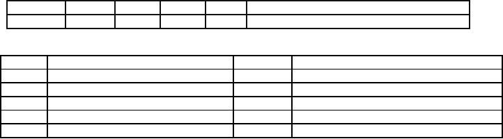
Meaning
Meaning
Symbol
Symbol
Replication
Remainder
after integer
division
α
%
Concatenation
Logical
AND
©
&
Conditional
constructs (IF-THEN)
Logical
OR
:
~
Sequential
constructs
Logical
NOT or complement
;
!
Concurrent
constructs
LOAD or
assignment operator
,
←
Page
119
Last
Modified: 01-Nov-06

Advanced Computer
Architecture-CS501
Limitations
of the ORIGINAL EAGLE
ISA
The
original 16-bit ISA of EAGLE
has severe limitations, as
outlined below.
1.
Use of R0 as accumulator
In most
cases, the register R0 is being
used as one of the
source
operands as well as the destination
operand. Thus,
R0 has essentially
become the accumulator. However,
this
will
require some additional
instructions for use with
the
accumulator.
That should not be a problem
since there are
some unused
op-codes available in the
ISA.
2.
Unequal and inefficient op-code
assignment
The designer has
apparently tried to extend the
number of
operations in the
ISA by op-code extension.
Op-code 11111
combine
three additional bits of the
instruction for five
instructions:
unconditional
branch, nop, halt, reset
and
init.while
there is a possibility of including
three more
instructions in
this scheme, notice that
op-code 00 for
register to
register mov is causing a
"loss" of eight "slots"
in
the original
5-bit op-code assignment.
(The mov instruction
is, in
effect, using eight
op-codes). A better way would be
to
assign a
5-bit op-code to mov and use the
remaining op-
codes
for other
instructions.
3.
Number of the operands
Looking at the
mov
instruction
again, it can be noted
that
this is the
only instruction that uses
two operands, and thus
requires a
separate format (Format#1)
for instruction
enoding. If the
job of this instruction is
given to two
instructions
(copy register to accumulator, and
copy
accumulator to
register), the number of instruction
formats
can be reduced
thereby, simplifying the assembler and
the
compiler
needed for this
ISA.
4.
Use of registers for branch
conditions
Note
that one of the GPRs is being
used to hold the branch
condition. This would
require
that
the result from the
accumulator be copied to the particular
GPR before the
branch
instruction.
Including flags with the
ALSU can eliminate this
restriction
The
Modified EAGLE
The
modified EAGLE is an improved
version of the processor
EAGLE. As we have
already
discussed, there were
several limitations in EAGLE, and
these have been
remedied in
the modified EAGLE
processor.
Page
120
Last
Modified: 01-Nov-06
Advanced Computer
Architecture-CS501
Introduction
The
modified EAGLE is also an
accumulator-based processor. It is a simple,
yet complex
enough to
illustrate the various concepts of a
processor design.
The
modified EAGLE is characterized
by
· A special
purpose register, the 16-bit
accumulator: ACC
· 8
General Purpose Registers of the
CPU: R0, R1, ..., R7;
16-bits each
· Two
16-bit system registers transparent to
the programmer are the
Program
Counter
(PC) and the Instruction
Register (IR).
· Memory
word size: 16 bits
· Memory
space size: 216 bytes
· Memory
organization: 216
x 8
bits
· Memory
is accessed in 16 bit words
(i.e., 2 byte chunks)
· Little-endian
byte storage is
employed
Page
121
Last
Modified: 01-Nov-06
Advanced Computer
Architecture-CS501
Programmer's
View of the Modified
EAGLE
The
given
figure
is
the
programmer's
view
of
the
modified
EAGLE processor.
Notation
The
notation that is employed
for
the
study of the modified
EAGLE
is the
same as the original
EAGLE
processor.
Recall that we know
that:
Enclosing
the register name in
square
brackets refers to register
contents;
for instance, R [3] means
contents of register
R3.
Enclosing
the location address in
square brackets, preceded by `M', lets us
refer to
memory
contents. Hence M
[8] means contents of memory
location 8.
As little
endian storage is employed, a
memory
word at
address x is defined as the
16
bits at
address x+1 and x. For
instance, the bits at memory
location 9,8 define
the
memory
word at location 8. So employing
the special notation for
16-bit memory words,
we
have
M[8]<15...0>:=M[9]©M[8]
Where
is used to
represent
concatenation
The
memory word access and copy
to a
register
is shown in the
figure.
Features
The
following features characterize
the
modified
EAGLE processor.
· Instruction
length is variable. Instructions
are either 8 bits or 16
long, i.e.,
instruction
size is either half a word or 1
word.
· The
instructions may have either
one or two operands.
· The
only way to
access
memory is
through load and
store
instructions
· Limited
addressing modes are
supported
Note
that these properties are
the same
as the
original EAGLE
processor
Instruction
formats
There
are four instruction format
types
in the
modified EAGLE processor
as
well.
These are
Page
122
Last
Modified: 01-Nov-06
Advanced Computer
Architecture-CS501
Encoding
of the General Purpose
Registers
The
encoding for the
eight
GPRs is
shown in the table.
These are
binary codes
assigned
to the registers
that will
be used in place of
the
ra, rb in the actual
instructions
of the modified
processor
EAGLE.
ISA
for
the
Modified
EAGLE
(16-bit
registers, 16-bit ACC, PC and IR, 8-bit
wide memory, 256 I/O
ports)
Operand
Constant
Mnemonic
Op-code
Format
Behavioral RTL
3bits
8
bits
Unused
00111
addi
00100
ra
C1
X
ACC
←
R[ra]
+(8αC1<7>)©C1;
subi
00101
ra
C1
X
ACC
←
R[ra] -
(8αC1<7>)©C1;
shiftl
01010
ra
C1
X
R[ra]
←
R[ra]<(15-n)..0>©(nα0);
shiftr
01011
ra
C1
X
R[ra]
←
(nα0)©R[ra]<15...n>;
andi
01100
ra
C1
X
ACC
←
R[ra]
& (8αC1<7>)©C1;
ori
01101
ra
C1
X
ACC
←
R[ra] ~
(8αC1<7>)©C1;
asr
01110
ra
C1
X
R[ra]
←
(nαR[ra}<15>)©R[ra]<15...n>;
in
10001
ra
C1
X
R[ra]
←IO[C1];
ldacc
10010
ra
C1
X
ACC
←M[R[ra]
+(8αC1<7>)©C1];
movir
10100
ra
C1
X
R[ra]
←
(8αC1<7>)©C1;
out
10101
ra
C1
X
IO[C1]
←R[ra];
stacc
10111
ra
C1
X
M[R[ra]
+(8αC1<7>)©C1]← ACC;
movia
10011
C1
W
ACC
←
(8αC1<7>)©C1;
br
11000
-
C1
W
PC ← PC + 8αC1<7>)©C1;
brn
11001
C1
W
(S=1): PC
←
PC+(8αC1<7>)©C1;
brnz
11010
C1
W
(Z=0): PC
←
PC+(8αC1<7>)©C1;
brp
11011
C1
W
(S=0): PC
←
PC+(8αC1<7>)©C1;
brz
11100
C1
W
(Z=1): PC
←
PC+(8αC1<7>)©C1;
add
00000
ra
-
Y
ACC
←
ACC +
R[ra];
sub
00001
ra
-
Y
ACC
←
ACC -
R[a];
ACC
←
(R[ra]
©ACC)/R[a],
div
00010
ra
-
Y
R[ra]
←
(R[ra]
©ACC)%R[a];
mul
00011
ra
-
Y
R[ra]
ACC ← R[ra]*ACC;
and
01000
ra
-
Y
ACC
←
ACC &
R[ra];
or
01001
ra
-
Y
ACC
←
ACC ~
R[ra];
not
01111
ra
-
Y
ACC
←
!(
R[ra]);
a2r
10000
ra
-
Y
R[ra]
←
ACC
r2a
10110
ra
Y
ACC
←
R[ra]
cla
00110
Z
ACC
←
0;
halt
11101
-
-
Z
RUN← 0;
Page
123
Last
Modified: 01-Nov-06
Advanced Computer
Architecture-CS501
nop
11110
-
-
Z
;
reset
11111
-
-
Z
TBD;
Symbol
Meaning
Symbol
Meaning
α
Replication
%
Remainder
after integer
division
©
Concatenation
&
Logical
AND
:
Conditional
constructs (IF-THEN)
~
Logical
OR
;
Sequential
constructs
!
Logical
NOT or complement
,
Concurrent
constructs
←
LOAD or
assignment operator
Page
124
Last
Modified: 01-Nov-06
Table of Contents:
- Computer Architecture, Organization and Design
- Foundations of Computer Architecture, RISC and CISC
- Measures of Performance SRC Features and Instruction Formats
- ISA, Instruction Formats, Coding and Hand Assembly
- Reverse Assembly, SRC in the form of RTL
- RTL to Describe the SRC, Register Transfer using Digital Logic Circuits
- Thinking Process for ISA Design
- Introduction to the ISA of the FALCON-A and Examples
- Behavioral Register Transfer Language for FALCON-A, The EAGLE
- The FALCON-E, Instruction Set Architecture Comparison
- CISC microprocessor:The Motorola MC68000, RISC Architecture:The SPARC
- Design Process, Uni-Bus implementation for the SRC, Structural RTL for the SRC instructions
- Structural RTL Description of the SRC and FALCON-A
- External FALCON-A CPU Interface
- Logic Design for the Uni-bus SRC, Control Signals Generation in SRC
- Control Unit, 2-Bus Implementation of the SRC Data Path
- 3-bus implementation for the SRC, Machine Exceptions, Reset
- SRC Exception Processing Mechanism, Pipelining, Pipeline Design
- Adapting SRC instructions for Pipelined, Control Signals
- SRC, RTL, Data Dependence Distance, Forwarding, Compiler Solution to Hazards
- Data Forwarding Hardware, Superscalar, VLIW Architecture
- Microprogramming, General Microcoded Controller, Horizontal and Vertical Schemes
- I/O Subsystems, Components, Memory Mapped vs Isolated, Serial and Parallel Transfers
- Designing Parallel Input Output Ports, SAD, NUXI, Address Decoder , Delay Interval
- Designing a Parallel Input Port, Memory Mapped Input Output Ports, wrap around, Data Bus Multiplexing
- Programmed Input Output for FALCON-A and SRC
- Programmed Input Output Driver for SRC, Input Output
- Comparison of Interrupt driven Input Output and Polling
- Preparing source files for FALSIM, FALCON-A assembly language techniques
- Nested Interrupts, Interrupt Mask, DMA
- Direct Memory Access - DMA
- Semiconductor Memory vs Hard Disk, Mechanical Delays and Flash Memory
- Hard Drive Technologies
- Arithmetic Logic Shift Unit - ALSU, Radix Conversion, Fixed Point Numbers
- Overflow, Implementations of the adder, Unsigned and Signed Multiplication
- NxN Crossbar Design for Barrel Rotator, IEEE Floating-Point, Addition, Subtraction, Multiplication, Division
- CPU to Memory Interface, Static RAM, One two Dimensional Memory Cells, Matrix and Tree Decoders
- Memory Modules, Read Only Memory, ROM, Cache
- Cache Organization and Functions, Cache Controller Logic, Cache Strategies
- Virtual Memory Organization
- DRAM, Pipelining, Pre-charging and Parallelism, Hit Rate and Miss Rate, Access Time, Cache
- Performance of I/O Subsystems, Server Utilization, Asynchronous I/O and operating system
- Difference between distributed computing and computer networks
- Physical Media, Shared Medium, Switched Medium, Network Topologies, Seven-layer OSI Model