 |
Real Time Interrupts and Hardware Interfacing |
| << Software Interrupts: Hooking an Interrupt, BIOS and DOS Interrupts |
| Debug Interrupts: Debugger using single step interrupt, breakpoint interrupt >> |

9
Real Time Interrupts
and
Hardware
Interfacing
9.1.
HARDWARE INTERRUPTS
The
same mechanism as discussed in
the previous chapter is used
for real
interrupts
that are generated by
external hardware. However
there is a single
pin
outside the processor called
the INT pin that is used by
external
hardware
to generate interrupts. The
detailed operation that
happens outside
the
process when an interrupt is generated is
complex and only a
simplified
view
will be discussed here; the
view that is relevant to an
assembly language
programmer.
There are many external
devices that need the
processor's
attention
like the keyboard, hard
disk, floppy disk, sound
card. All of them
need
real time interrupts at some
point in their operation.
For example if a
program
is busy in some calculations
for three minutes the
key strokes that
are hit
meanwhile should not be
wasted. Therefore when a key is
pressed,
the INT
signal is sent, an interrupt
generated and the interrupt
handler
stores
the key for later
use. Similarly when the
printer is busy printing
we
cannot
send it more data. As soon
as it gets free from the
previous job it
interrupts
the processor to inform that
it is free now. There are
many other
examples
where the processor needs to
be informed of an external event.
If
the
processor actively monitors
all devices instead of being
automatically
interrupted
then it there won't be any
time to do meaningful
work.
Since
there are many devices
generating interrupts and
there is only one
pin
going inside the processor
and one pin cannot be
technically derived by
more
than one source a controller
is used in between called
the
Programmable
Interrupt Controller (PIC). It
has eight input signals and
one
output
signal. It assigns priorities to
its eight input pins from 0
to 7 so that if
more
than one interrupt comes at
the same times, the
highest priority one
is
forwarded
and the rest are
held till that is serviced.
The rest are
forwarded
one by
one according to priority
after the highest priority
one is completed.
The
original IBM XT computer had
one PIC so there were 8
possible interrupt
sources.
However IBM AT and later
computers have two PIC
totaling 16
possible
interrupt sources. They are
arrange is a special cascade
master
slave
arrangement so that only one
output signal comes towards
the
processor.
However we will concentrate on the
first interrupt controller
only.
The
priority can be understood with
the following example.
Consider eight
parallel
switches which are all
closed and connected to form
the output
signal.
When a signal comes on one
of the switches, it is passed on to
the
output
and this switch and
all below it are opened so
that no further
signals
can
pass through it. The
higher priority switches are
still closed and
the
signal
on them can be forwarded. When
the processor signals that
it is
finished
with the processing the
switches are closed again
and any waiting
interrupts
may be forwarded. The way the
processor signals ending of
the
interrupt
service routine is by using a
special mechanism discussed
later.
The
eight input signals to the
PIC are called Interrupt
Requests (IRQ). The
eight
lines are called IRQ 0 to
IRQ 7. These are the input
lines of the 8451.�
For
example IRQ 0 is derived by a
timer device. The timer
device keeps
8451 is
the technical number of the
PIC.
�
Computer
Architecture & Assembly Language
Programming
Course
Code: CS401
CS401@vu.edu.pk
generating
interrupts with a specified frequency.
IRQ 1 is derived by
the
keyboard
when generates an interrupts when a key
is pressed or released.
IRQ 2
is the cascading interrupt
connected to the output of
the second 8451
in the
machine. IRQ 3 is connected to
serial port COM 2 while IRQ
4 is
connected
to serial port COM 1. IRQ 5 is
used by the sound card or
the
network
card or the modem. An IRQ
conflict means that two
devices in the
system
want to use the same IRQ
line. IRQ 6 is used by the
floppy disk drive
while
IRQ 7 is used by the
parallel port.
Each
IRQ is mapped to a specific
interrupt in the system.
This is called the
IRQ to
INT mapping. IRQ 0 to IRQ 7
are consecutively mapped on
interrupts
8 to F.
This mapping is done by the
PIC and not the
processor. The actual
mechanism
fetches one instruction from
the PIC whenever the INT pin
is
signaled
instead of the memory. We
can program the PIC to
generate a
different
set of interrupts on the
same interrupt requests.
From the
perspective
of an assembly language programmer an
IRQ 0 is translated
into
an INT 8
without any such instruction
in the program and that's
all.
Therefore
an IRQ 0, the highest
priority interrupt, is generated by
the timer
chip at
a precise frequency and the
handler at INT 8 is invoked which
updates
the system time. A key
press generates IRQ 1 and
the INT 9 handler
is
invoked which stores this
key. To handler the timer
and keyboard
interrupts
one can replace the
vectors corresponding to interrupt 8
and 9
respectively.
For example if the timer
interrupt is replaced and
the floppy is
accessed
by some program, the floppy
motor and its light will
remain on for
ever as
in the normal case it is
turned off by the timer
interrupt after two
seconds
in anticipation that another
floppy access might be
needed
otherwise
the time motor takes to
speed up will be needed
again.�
We have
seen that an interrupt
request from a device enters
the PIC as an
IRQ,
from there it reaches the
INT pin of the processor, the
processor
receives
the interrupt number from
the PIC, generates the
designated
interrupt,
and finally the interrupt
handler gain control and
can do whatever
is
desired. At the end of
servicing the interrupt the
handler should inform
the
PIC
that it is completed so that
lower priority interrupts
can be sent from
the
PIC.
This signal is called an End Of
Interrupt (EOI) signal and
is sent
through
the I/O ports of the
interrupt controller.
9.2.
I/O PORTS
There
are hundreds of peripheral
devices in the system, PIC
is one
example.
The processor needs to
communicate with them, give
and take data
from
them, otherwise their
presence is meaningless. Memory
has a totally
different
purpose. It contains the
program to be executed and
its data. It
does
not control any hardware.
For communicating with peripheral
devices
the
processor uses I/O ports.
There are only two
operations with the
external
world
possible, read or write.
Similarly with I/O ports the
processor can read
or
write an I/O port. When an I/O
port is read or written to,
the operation is
not as
simple as it happens in memory.
Some hardware changes
it
functionality
or performs some operation as a
result.
IBM PC
has separate memory address
space and peripheral address
space.
Some
processors use memory mapped
I/O in which case designated
memory
cells
work as ports for specific
devices. In case of Intel a
special pin on the
control
bus signals whether the
current read or write is
from the memory
address
space or from the peripheral
address space. The same
address and
data
buses are used to select a
port and to read or write
data from that
port.
However
with I/O only the lower 16
bits of the address bus are
used meaning
that
there are a total of 65536
possible I/O ports. Now keyboard
has special
The
programs discussed from now
onwards in the book must be
executed
�
in pure
DOS and not in a DOS window
so that we are in total
control of the
PIC
and other devices.
106
Computer
Architecture & Assembly Language
Programming
Course
Code: CS401
CS401@vu.edu.pk
I/O
ports designated to it, PIC
has others, DMA, sound card,
network card,
each
has some ports.
If the
two address spaces are
differentiated in hardware, they must
also
have
special instructions to select
the other address space. We
have the IN
and
OUT instructions to read or
write from the peripheral
address space.
When
MOV is given the processor
selects the memory address
space, when
IN is
given the processor selects
the peripheral address
space.
IN and
OUT instructions
The IN
and OUT instructions have a
byte form and a word
form but the
byte
form is almost always used.
The source register in OUT
and destination
register
in IN is AL or AX depending on which form is
used. The port
number
can be
directly given in the
instruction if it fits in a byte
otherwise it has to
be
given in the DX register.
Port numbers for specific
devices are fixed by
the
IBM
standard. For example 20 and
21 are for PIC, 60 to 64 for
Keyboard, 378
for
the parallel port etc. A
few example of IN and OUT
are below:
in al,
0x21
mov dx,
0x378
in al, dx
out 0x21,
al
mov dx,
0x378
out dx, al
PIC
Ports
Programmable
interrupt controller has two
ports 20 and 21. Port 20 is
the
control
port while port 21 is the
interrupt mask register which can be
used
for
selectively enabling or disabling
interrupts. Each of the bits
at port 21
corresponds
to one of the IRQ lines. We
first write a small program
to disable
the
keyboard using this port. As
we know that the keyboard
IRQ is 1, we
place a
1 bit at its corresponding position. A 0
bit will enable an interrupt
and a 1
bit disables it. As soon as we
write it on the port
keyboard interrupts
will
stop arriving and the
keyboard will effectively be disabled.
Even Ctrl-Alt-
Del
would not work; the
reset power button has to be
used.
Example
9.1
001
; disable
keyboard
interrupt in PIC
mask register
002
[org
0x0100]
003
in
al,
0x21
; read interrupt
mask register
004
or
al, 2
; set bit for
IRQ2
005
out
0x21, al
; write back
mask register
006
007
mov
ax,
0x4c00
; terminate
program
008
int
0x21
After
this three line mini program
is executed the computer will
not
understand
anything else. Its ears are
closed. No keystrokes are
making their
way to
the processor. Ports always
make something happen on the
system. A
properly
designed system can launch a
missile on writing a bit on some
port.
Memory
is simple in that it is all
that it is. In ports every
bit has a meaning
that
changes something in the
system.
As we
previously discussed every
interrupt handler invoked
because
of an IRQ
must signal an EOI otherwise
lower priority interrupts
will
remain
disabled.
Keyboard
Controller
We will go in
further details of the
keyboard and its relation to
the
computer.
We will not discuss how the
keyboard communicates with
the
keyboard
controller in the computer
rather we will discuss how the
keyboard
107
Computer
Architecture & Assembly Language
Programming
Course
Code: CS401
CS401@vu.edu.pk
controller
communicates with the processor.
Keyboard is a collection of
labeled
buttons and every button is
designated a number (not the
ASCII
code).
This number is sent to the
processor whenever the key
is pressed.
From
this number called the
scan code the processor
understands which key
was
pressed. For each key
the scan code comes
twice, once for the
key press
and
once for the key
release. Both are scan
codes and differ in one bit
only.
The
lower seven bits contain
the key number while
the most significant bit
is
clear
in the press code and
set in the release code.
The IBM PC standard
gives a
table of the scan codes of
all keys.
If we
press Shift-A resulting in a
capital A on the screen, the
controller has
sent
the press code of Shift,
the press code of A, the
release code of A,
the
release
code of Shift and the
interrupt handler has
understood that this
sequence
should result in the ASCII
code of `A'. The `A' key
always produces
the
same scan code whether or
not shift is pressed. It is
the interrupt
handler's
job to remember that the
press code of Shift has
come and release
code
has not yet come
and therefore to change the
meaning of the
following
key
presses. Even the caps
lock key works the
same way.
An
interesting thing is that
the two shift keys on the
left and right side
of
the
keyboard produce different
scan codes. The standard way
implemented
in BIOS
is to treat that similarly.
That's why we always think of them
as
identical.
If we leave BIOS and talk
directly with the hardware we
can
differentiate
between left and right
shift keys with their scan
code. Now this
scan
code is available from the
keyboard data port which is
60. The keyboard
generates
IRQ 1 whenever a key is
pressed so if we hook INT 9 and
inside it
read
port 60 we can tell which of
the shift keys was
hit. Our first
program
will do
precisely this. It will output an L if
the left shift key was
pressed and
R if
the right one was
pressed. The hooking method
is the same as done
in
the
previous chapter.
Example
9.2
001
; differentiate left
and right shift keys with
scancodes
002
[org
0x0100]
003
jmp
start
004
005
; keyboard
interrupt service routine
006
kbisr:
push
ax
007
push
es
008
009
mov
ax,
0xb800
010
mov
es, ax
; point es to video
memory
011
012
in
al,
0x60
; read a char from
keyboard port
013
cmp
al,
0x2a
; is the key left
shift
014
jne
nextcmp
; no, try next
comparison
015
016
mov
byte [es:0],
'L'
; yes, print L at top
left
017
jmp
nomatch
; leave interrupt
routine
018
019
nextcmp:
cmp
al,
0x36
; is the key right
shift
020
jne
nomatch
; no, leave interrupt
routine
021
022
mov
byte [es:0],
'R'
; yes, print R at top
left
023
024
nomatch:
mov
al,
0x20
025
out
0x20, al
; send EOI to
PIC
026
027
pop
es
028
pop
ax
029
iret
030
031
start:
xor
ax, ax
032
mov
es, ax
;
point es to IVT
base
033
cli
;
disable
interrupts
034
mov
word [es:9*4],
kbisr
; store offset at
n*4
035
mov
[es:9*4+2],
cs
;
store segment at
n*4+2
036
sti
;
enable
interrupts
108
Computer
Architecture & Assembly Language
Programming
Course
Code: CS401
CS401@vu.edu.pk
037
038
l1:
jmp
l1
; infinite
loop
CLI
clears the interrupt flag to
disable the interrupt
system
033-036
completely.
The processor closes its
ears and does not
care about
the
state of the INT pin.
Interrupt hooking is done in
two
instructions,
placing the segment and
placing the offset. If
an
interrupt
comes in between and the
vector is in an indeterminate
state,
the system will go to a junk address
and eventually crash.
So
we stop
all interruptions while
changing a real time
interrupt vector.
We set
the interrupt flag
afterwards to renewable
interrupts.
The
program hangs in an infinite
loop. The only activity
can be
038
caused
by a real time interrupt.
The kbisr routine is not
called from
anywhere;
it is only automatically invoked as a
result of IRQ 1.
When
the program is executed the
left and right shift
keys can be
distinguished
with the L or R on the screen. As no
action was taken for
the
rest of
the keys, they are
effectively disabled and the
computer has to be
rebooted.
To check that the keyboard
is actually disabled we change
the
program
and add the INT 16 service 0
at the end to wait for an
Esc key press.
As soon
as Esc is pressed we want to terminate
our program.
Example
9.3
001
; attempt to terminate
program with Esc that hooks
keyboard interrupt
002
[org
0x0100]
003
jmp
start
004
005-029
;;;;; COPY LINES
005-029 FROM EXAMPLE 9.2 (kbisr)
;;;;;
030
031
start:
xor
ax, ax
032
mov
es, ax
;
point es to IVT
base
033
cli
;
disable
interrupts
034
mov
word [es:9*4],
kbisr
; store offset at
n*4
035
mov
[es:9*4+2],
cs
;
store segment at
n*4+2
036
sti
;
enable
interrupts
037
038
l1:
mov
ah, 0
; service 0 get
keystroke
039
int
0x16
; call BIOS
keyboard service
040
041
cmp al,
27
; is the Esc key
pressed
042
jne l1
; if no, check for
next key
043
044
mov ax,
0x4c00
; terminate
program
045
int
0x21
When
the program is executed the
behavior is same. Esc does
not work.
This is
because the original IRQ 1
handler was written by BIOS
that read the
scan
code, converted into an
ASCII code and stored in
the keyboard buffer.
The
BIOS INT 16 read the key
from there and gives in
AL. When we hooked
the
keyboard interrupt BIOS is no
longer in control, it has no
information, it
will
always see the empty
buffer and INT 16 will never
return.
Interrupt
Chaining
We can
transfer control to the
original BIOS ISR in the
end of our routine.
This
way the normal functioning of INT 16
can work as well. We can
retrieve
the
address of the BIOS routine
by saving the values in
vector 9 before
hooking
our routine. In the end of our
routine we will jump to this
address
using a
special indirect form of the
JMP FAR instruction.
Example
9.4
109
Computer
Architecture & Assembly Language
Programming
Course
Code: CS401
CS401@vu.edu.pk
001
; another attempt to terminate
program with Esc that
hooks
002
; keyboard
interrupt
003
[org
0x100]
004
jmp
start
005
006
oldisr:
dd
0
; space for saving
old isr
007
008
; keyboard
interrupt service routine
009
kbisr:
push
ax
010
push
es
011
012
mov
ax,
0xb800
013
mov
es, ax
; point es to video
memory
014
015
in
al,
0x60
; read a char from
keyboard port
016
cmp
al,
0x2a
; is the key left
shift
017
jne
nextcmp
; no, try next
comparison
018
019
mov
byte [es:0],
'L'
; yes, print L at top
left
020
jmp
nomatch
; leave interrupt
routine
021
022
nextcmp:
cmp
al,
0x36
; is the key right
shift
023
jne
nomatch
; no, leave interrupt
routine
024
025
mov
byte [es:0],
'R'
; yes, print R at top
left
026
027
nomatch:
;
mov
al,
0x20
028
; out
0x20, al
029
030
pop
es
031
pop
ax
032
jmp far
[cs:oldisr]
; call the original
ISR
033
; iret
034
035
start:
xor
ax, ax
036
mov
es, ax
; point es to IVT
base
037
mov
ax,
[es:9*4]
038
mov
[oldisr],
ax
; save offset of
old routine
039
mov
ax,
[es:9*4+2]
040
mov
[oldisr+2],
ax
;
save
segment of old routine
041
cli
;
disable
interrupts
042
mov
word [es:9*4],
kbisr
; store offset at
n*4
043
mov
[es:9*4+2],
cs
;
store segment at
n*4+2
044
sti
;
enable
interrupts
045
046
l1:
mov
ah, 0
; service 0 get
keystroke
047
int
0x16
; call BIOS
keyboard service
048
049
cmp al,
27
; is the Esc key
pressed
050
jne l1
; if no, check for
next key
051
052
mov ax,
0x4c00
; terminate
program
053
int
0x21
EOI is no
longer needed as the
original BIOS routine will
have it at
027-028
its
end.
IRET
has been removed and an
unconditional jump is introduced.
At
033
time of
JMP the stack has the
exact formation as was when
the
interrupt
came. So the original BIOS
routine's IRET will take
control
to the
interrupted program. We have
been careful in restoring
every
register
we modified and retained the
stack in the same form as
it
was at
the time of entry into
the routine.
When
the program is executed L
and R are printed as desired
and Esc
terminates
the program as well. Normal
commands like DIR work now
and
shift
keys still show L and R as
our routine did even after
the termination of
our
program. Now start some
application like the editor,
it open well but as
soon as
a key is pressed the
computer crashes.
Actually
our hooking and chaining was
fine. When Esc was pressed
we
signaled
DOS that our program has
terminated. DOS will take
all our
110
Computer
Architecture & Assembly Language
Programming
Course
Code: CS401
CS401@vu.edu.pk
memory
as a result. The routine is
still in memory and
functioning but the
memory
is free according to DOS. As
soon as we load EDIT the
same memory
is
allocated to EDIT and our routine as
overwritten. Now when a key is
pressed
our routine's address is in the
vector but at that address
some new
code is
placed that is not intended
to be an interrupt handler. That may
be
data or
some part of the EDIT
program. This results in
crashing the
computer.
Unhooking
Interrupt
We now
add the interrupt restoring
part to our program. This
code resets
the
interrupt vector to the
value it had before the
start of our program.
Example
9.5
001
; terminate
program with Esc that hooks
keyboard interrupt
002
[org
0x100]
003
jmp
start
004
005
oldisr:
dd
0
; space for saving
old isr
006
007-032
;;;;; COPY LINES
005-029 FROM EXAMPLE 9.4 (kbisr)
;;;;;
033
034
start:
xor
ax, ax
035
mov
es, ax
; point es to IVT
base
036
mov
ax,
[es:9*4]
037
mov
[oldisr],
ax
; save offset of
old routine
038
mov
ax,
[es:9*4+2]
039
mov
[oldisr+2],
ax
;
save
segment of old routine
040
cli
;
disable
interrupts
041
mov
word [es:9*4],
kbisr
; store offset at
n*4
042
mov
[es:9*4+2],
cs
;
store segment at
n*4+2
043
sti
;
enable
interrupts
044
045
l1:
mov
ah, 0
; service 0 get
keystroke
046
int
0x16
; call BIOS
keyboard service
047
048
cmp al,
27
; is the Esc key
pressed
049
jne l1
; if no, check for
next key
050
051
mov
ax,
[oldisr]
;
read old offset in
ax
052
mov
bx,
[oldisr+2]
;
read old segment
in bx
053
cli
;
disable
interrupts
054
mov
[es:9*4],
ax
;
restore old offset from
ax
055
mov
[es:9*4+2],
bx
;
restore old
segment from bx
056
sti
;
enable
interrupts
057
058
mov ax,
0x4c00
; terminate
program
059
int
0x21
9.3.
TERMINATE AND STAY
RESIDENT
We
change the display to show L
only while the left
shift is pressed and
R
only
while the right shift is
pressed to show the use of
the release codes. We
also
changed that shift keys
are not forwarded to BIOS.
The effect will be
visible
with A and Shift-A both
producing small `a' but caps
lock will work.
There
is one major difference from
all the programs we have
been writing
till
now. The termination is done
using INT 21 service 31 instead of INT
21
service
4C. The effect is that
even after termination the
program is there and
is
legally there.
Example
9.6
001
; TSR to
show status of shift keys on top left of
screen
002
[org
0x0100]
003
jmp
start
004
005
oldisr:
dd
0
; space for saving
old isr
006
111
Computer
Architecture & Assembly Language
Programming
Course
Code: CS401
CS401@vu.edu.pk
007
; keyboard
interrupt service routine
008
kbisr:
push
ax
009
push
es
010
011
mov
ax,
0xb800
012
mov
es, ax
; point es to video
memory
013
014
in
al,
0x60
; read a char from
keyboard port
015
cmp
al,
0x2a
; has the left
shift pressed
016
jne
nextcmp
; no, try next
comparison
017
018
mov
byte [es:0],
'L'
; yes, print L at first
column
019
jmp
exit
; leave interrupt
routine
020
021
nextcmp:
cmp
al,
0x36
; has the right
shift pressed
022
jne
nextcmp2
; no, try next
comparison
023
024
mov
byte [es:0],
'R'
; yes, print R at
second column
025
jmp
exit
; leave interrupt
routine
026
027
nextcmp2:
cmp
al,
0xaa
; has the left
shift released
028
jne
nextcmp3
; no, try next
comparison
029
030
mov
byte [es:0], '
'
; yes, clear the first
column
031
jmp
exit
; leave interrupt
routine
032
033
nextcmp3:
cmp
al,
0xb6
; has the right
shift released
034
jne
nomatch
; no, chain to old
ISR
035
036
mov
byte [es:2], '
'
; yes, clear the
second column
037
jmp
exit
; leave interrupt
routine
038
039
nomatch:
pop
es
040
pop
ax
041
jmp
far
[cs:oldisr]
; call the original
ISR
042
043
exit:
mov
al,
0x20
044
out
0x20, al
; send EOI to
PIC
045
046
pop
es
047
pop
ax
048
iret
; return from
interrupt
049
050
start:
xor
ax, ax
051
mov
es, ax
; point es to IVT
base
052
mov
ax,
[es:9*4]
053
mov
[oldisr],
ax
; save offset of
old routine
054
mov
ax,
[es:9*4+2]
055
mov
[oldisr+2],
ax
;
save
segment of old routine
056
cli
;
disable
interrupts
057
mov
word [es:9*4],
kbisr
; store offset at
n*4
058
mov
[es:9*4+2],
cs
;
store segment at
n*4+2
059
sti
;
enable
interrupts
060
061
mov
dx, start
; end of resident
portion
062
add
dx, 15
; round up to next
para
063
mov
cl, 4
064
shr
dx, cl
; number of
paras
065
mov
ax,
0x3100
; terminate and
stay resident
066
int
0x21
When
this program is executed the
command prompt immediately
comes.
DIR can
be seen. EDIT can run and
keypresses do not result in a
crash. And
with
all that left and
right shift keys shown L
and R on top left of the
screen
while
they are pressed but the
shift keys do not work as
usual since we did
not
forwarded the key to BIOS.
This is selective
chaining.
112
Computer
Architecture & Assembly Language
Programming
Course
Code: CS401
CS401@vu.edu.pk
To
understand Terminate
and
Stay Resident
(TSR)
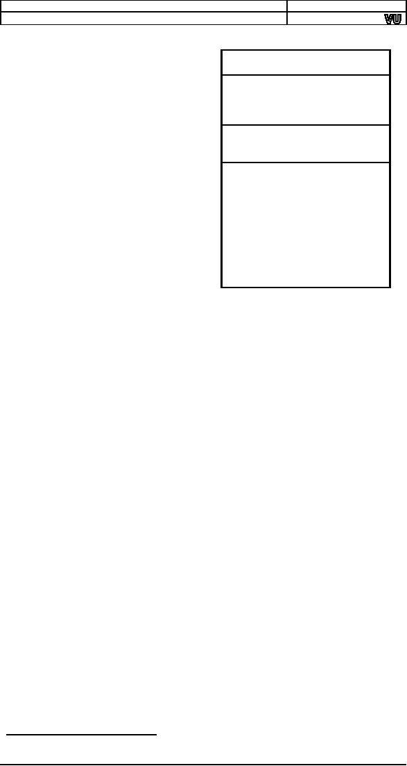
0
IVT
programs
the DOS memory
formation
and
allocation
BIOS
Data Area, DOS
Data
procedure
must
be
Area,
IO.SYS, MSDOS.SYS,
understood.
At
physical
Device
Drivers
address
zero is the interrupt
vector
table. Above it are
the
COMMAND.COM
BIOS
data area, DOS
data
area,
IO.SYS, MSDOS.SYS and
other
device drivers. In the
end
Transient
Program Area
(TPA)
there
is
COMMAND.COM
command
interpreter.
The
remaining
space is called the
transient
program area as
programs
are loaded
and
executed
in this area and
the
space
reclaimed on their
exit.
A
freemem pointer in
DOS
points
where the free
memory
640K
begins.
When DOS loads a
program
the freemem pointer is moved
to the end of memory, all
the
available
space is allocated to it,
and when it exits the
freemem pointer
comes
back to its original place
thereby reclaiming all
space. This action is
initiated
by the DOS service
4C.
The
second method to legally
terminate a program and give
control back to
DOS is
using the service 31.
Control is still taken back
but the memory
releasing
part is modified. A portion of
the allocated memory can be
retained.
So the
difference in the two methods is
that the freemem pointer
goes back to
the
original place or a designated
number of bytes ahead of
that old position.
Remember
that our program crashed
because the interrupt
routine was
overwritten.
If we can tell DOS not to
reclaim the memory of the
interrupt
routine,
then it will not crash. In
the last program we have
told DOS to make
a
number of bytes resident. It
becomes a part of the
operation system, an
extension
to it. Just like DOSKEY� is an extension to the
operation system.
The
number of paragraphs to reserve is
given in the DX register.
Paragraph
is a unit
just like byte, word,
and double word. A paragraph
is 16 bytes.
Therefore
we can reserve in multiple of 16
bytes. We write TSRs in such
a
way
that the initialization code
and data is located at the
end as it is not
necessary
to make it resident and
therefore to save
space.
To
calculate the number of
paragraphs a label is placed
after the last
line
that is
to be made resident. The
value of that label is the
number of bytes
needed
to be made resident. A simple
division by 16 will not give
the correct
number
of paras as we want our answer to be
rounded up and not down.
For
example
100 bytes should need 7
pages but division gives 6
and a remainder
of 4. A
standard technique to get
rounded up integer division is to
add
divisor-1
to the dividend and then
divide. So we add 15 to the
number of
bytes
and then divide by 16. We
use shifting for division as
the divisor is a
power
of 2. We use a form of SHR that
places the count in the CL
register so
that we
can shift by 4 in just two
instructions instead of 4 if we shift
one by
one.
In our
program anything after start
label is not needed after
the program
has
become a TSR. We can observe
that our program has become
a part of
DOS by
giving the following
command.
mem
/c
DOSKEY
is a TSR that shows the
previous commands on the
command
�
prompt
with up and down arrows and
allows editing of the
command
113
Computer
Architecture & Assembly Language
Programming
Course
Code: CS401
CS401@vu.edu.pk
This
command displays all
currently loaded drivers and
the current state
of
memory. We will be able to see our
program in the list of DOS
drivers.
9.4.
PROGRAMMABLE INTERVAL
TIMER
Another
very important peripheral
device is the Programmable
Interval
Timer
(PIT), the chip numbered
8254. This chip has a
precise input
frequency
of 1.19318 MHz. This frequency is
fixed regardless of the
processor
clock.
Inside the chip is a 16bit
divisor which divides this input
frequency
and
the output is connected to
the IRQ 0 line of the
PIC. The special
number
0 if
placed in the divisor means
a divisor of 65536 and not
0. The standard
divisor
is 0 unless we change it.
Therefore by default IRQ 0 is
generated
1193180/65536=18.2
times per second. This is
called the timer tick.
There is
an
interval of about 55ms between two
timer ticks. The system
time is
maintained
with the timer interrupt.
This is the highest priority
interrupt
and
breaks whatever is executing.
Time can be maintained with
this
interrupt
as this frequency is very
precise and is part of the
IBM standard.
When
writing a TSR we give
control back to DOS so TSR
activation,
reactivation
and action is solely
interrupt based, whether
this is a hardware
interrupt
or a software one. Control is
never given back; it must be
caught,
just
like we caught control by
hooking the keyboard
interrupt. Our next
example
will hook the timer
interrupt and display a tick
count on the screen.
Example
9.7
001
; display a tick count on the
top right of screen
002
[org
0x0100]
003
jmp
start
004
005
tickcount:
dw
0
006
007
; subroutine to print a
number at top left of screen
008
; takes the number
to be printed as its parameter
009
printnum:
push
bp
010
mov bp,
sp
011
push
es
012
push
ax
013
push
bx
014
push
cx
015
push
dx
016
push
di
017
018
mov
ax,
0xb800
019
mov
es,
ax
;
point es to video
base
020
mov
ax,
[bp+4]
;
load number in
ax
021
mov
bx,
10
;
use
base 10 for division
022
mov
cx,
0
;
initialize count of
digits
023
024
nextdigit:
mov
dx, 0
;
zero upper half of
dividend
025
div
bx
;
divide by
10
026
add
dl,
0x30
;
convert digit into ascii
value
027
push
dx
;
save ascii value
on stack
028
inc
cx
;
increment count of
values
029
cmp
ax, 0
;
is the quotient
zero
030
jnz
nextdigit
;
if no divide it
again
031
032
mov
di,
140
; point di to 70th
column
033
034
nextpos:
pop
dx
;
remove a digit
from the stack
035
mov
dh,
0x07
;
use normal
attribute
036
mov
[es:di], dx
;
print char on
screen
037
add
di, 2
;
move to next
screen location
038
loop
nextpos
;
repeat for all digits on
stack
039
040
pop
di
041
pop
dx
042
pop
cx
043
pop
bx
044
pop
ax
114
Computer
Architecture & Assembly Language
Programming
Course
Code: CS401
CS401@vu.edu.pk
045
pop
es
046
pop
bp
047
ret
2
048
049
; timer interrupt service
routine
050
timer:
push
ax
051
052
inc word
[cs:tickcount]; increment tick count
053
push
word [cs:tickcount]
054
call
printnum
; print tick
count
055
056
mov
al,
0x20
057
out
0x20, al
; end of
interrupt
058
059
pop
ax
060
iret
; return from
interrupt
061
062
start:
xor
ax, ax
063
mov
es, ax
; point es to IVT
base
064
cli
; disable
interrupts
065
mov
word [es:8*4],
timer; store offset at n*4
066
mov
[es:8*4+2],
cs
; store segment at
n*4+2
067
sti
; enable
interrupts
068
069
mov
dx, start
; end of resident
portion
070
add
dx, 15
; round up to next
para
071
mov
cl, 4
072
shr
dx, cl
; number of
paras
073
mov
ax,
0x3100
; terminate and
stay resident
074
int
0x21
When we
execute the program the
counter starts on the
screen. Whatever
we do,
take directory, open EDIT,
the debugger etc. the
counter remains
running
on the screen. No one is
giving control to the
program; the program
is
getting executed as a result of
timer generating INT 8 after
every 55ms.
Our
next example will hook both
the keyboard and timer
interrupts. When
the
shift key is pressed the
tick count starts
incrementing and as soon as
the
shift
key is released the tick
count stops. Both interrupt
handlers are
communicating
through a common variable.
The keyboard interrupt sets
this
variable
while the timer interrupts
modifies its behavior
according to this
variable.
Example
9.8
001
; display a tick count while
the left shift key is down
002
[org
0x0100]
003
jmp
start
004
005
seconds:
dw
0
006
timerflag:
dw
0
007
oldkb:
dd
0
008
009-049
;;;;; COPY LINES
007-047 FROM EXAMPLE 9.7 (printnum)
;;;;;
050
051
; keyboard
interrupt service routine
052
kbisr:
push
ax
053
054
in
al,
0x60
; read char from
keyboard port
055
cmp
al,
0x2a
; has the left
shift pressed
056
jne
nextcmp
; no, try next
comparison
057
058
cmp
word
[cs:timerflag], 1; is the flag already set
059
je
exit
; yes, leave the
ISR
060
061
mov
word
[cs:timerflag], 1; set flag to start printing
062
jmp
exit
; leave the
ISR
063
064
nextcmp:
cmp
al,
0xaa
; has the left
shift released
065
jne
nomatch
; no, chain to old
ISR
066
067
mov
word
[cs:timerflag], 0; reset flag to stop printing
115
Computer
Architecture & Assembly Language
Programming
Course
Code: CS401
CS401@vu.edu.pk
068
jmp
exit
; leave the interrupt
routine
069
070
nomatch:
pop
ax
071
jmp
far
[cs:oldkb]
; call original
ISR
072
073
exit:
mov
al,
0x20
074
out
0x20, al
; send EOI to
PIC
075
076
pop
ax
077
iret
; return from
interrupt
078
079
; timer interrupt service
routine
080
timer:
push
ax
081
082
cmp
word
[cs:timerflag], 1 ; is the printing flag set
083
jne
skipall
; no, leave the
ISR
084
085
inc word
[cs:seconds]
; increment tick
count
086
push
word [cs:seconds]
087
call
printnum
; print tick
count
088
089
skipall:
mov
al,
0x20
090
out
0x20, al
; send EOI to
PIC
091
092
pop
ax
093
iret
; return from
interrupt
094
095
start:
xor
ax, ax
096
mov
es, ax
; point es to IVT
base
097
mov
ax,
[es:9*4]
098
mov
[oldkb], ax
; save offset of
old routine
099
mov
ax,
[es:9*4+2]
100
mov
[oldkb+2],
ax
;
save
segment of old routine
101
cli
;
disable
interrupts
102
mov
word
[es:9*4],
kbisr
; store offset at
n*4
103
mov
[es:9*4+2],
cs
;
store segment at
n*4+2
104
mov
word
[es:8*4],
timer
; store offset at
n*4
105
mov
[es:8*4+2],
cs
;
store segment at
n*4+
106
sti
;
enable
interrupts
107
108
mov
dx, start
; end of resident
portion
109
add
dx, 15
; round up to next
para
110
mov
cl, 4
111
shr
dx, cl
; number of
paras
112
mov
ax,
0x3100
; terminate and
stay resident
113
int
0x21
This
flag is one when the timer
interrupt should increment
and zero
006
when it
should not.
As the
keyboard controller repeatedly
generates the press code if
the
058-059
release
code does not come in a
specified time, we have
placed a
check
to not repeatedly set it to
one.
Another
way to access TSR data is
using the CS override
instead of
058
initializing
DS. It is common mistake not
to initialize DS and
also
not put
in CS override in a real time
interrupt handler.
When we
execute the program and
the shift key is pressed,
the counter
starts
incrementing. When the key
is released the counter
stops. When it is
pressed
again the counter resumes
counting. As this is made as a
TSR any
other
program can be loaded and
will work properly alongside the
TSR.
9.5.
PARALLEL PORT
Computers
can control external
hardware through various
external ports
like
the parallel port, the
serial port, and the new
additions USB and
FireWire.
Using this, computers can be
used to control almost
anything. For
our
examples we will use the
parallel port. The parallel
port has two views,
the
connector that the external
world sees and the
parallel port
controller
116
Computer
Architecture & Assembly Language
Programming
Course
Code: CS401
CS401@vu.edu.pk
ports
through which the processor
communicates with the device
connected
to the
parallel port.
The
parallel port connector is a
25pin connector called
DB-25. Different
pins of
this connector have
different meanings. Some are
meaningful only
with
the printer**.
This is a bidirectional port so
there are some pins to
take
data
from the processor to the
parallel port and others to
take data from
the
parallel
port to the processor.
Important pins for our use
are the data
pins
from
pin 2 to pin 9 that take data
from the processor to the
device. Pin 10,
the
ACK pin, is normally used by
the printer to acknowledge
the receipt of
data
and show the willingness to
receive more data. Signaling
this pin
generates
IRQ 7 if enabled in the PIC
and in the parallel port
controller. Pin
18-25
are ground and must be
connected to the external
circuit ground to
provide
the common reference point
otherwise they won't
understand each
other
voltage levels. Like the
datum point in a graph this is
the datum point
of an
electrical circuit. The
remaining pins are not of
our concern in these
examples.
This is
the external view of the
parallel port. The processor
cannot see
these
pins. The processor uses
the I/O ports of the
parallel port
controller.
The
first parallel port
LPT1�� has ports
designated from 378 to 37A.
The first
port
378 is the data port. If we
use the OUT instruction on
this port, 1 bits
result
in a 5V signal on the corresponding pin
and a 0 bits result in a
0V
signal
on the corresponding
pin.
Port
37A is the control port. Our
interest is with bit 4 of this port
which
enables
the IRQ 7 triggering by the
ACK pin. We have attached a
circuit that
connects
8 LEDs with the parallel
port pins. The following
examples sends
the
scancode of the key pressed
to the parallel port so that
it is visible on
LEDs.
Example
9.9
001
; show
scancode on external LEDs connected
through parallel port
002
[org
0x0100]
003
jmp
start
004
005
oldisr:
dd
0
; space for saving
old ISR
006
007
; keyboard
interrupt service routine
008
kbisr:
push
ax
009
push
dx
010
011
in
al,
0x60
; read char from
keyboard port
012
mov
dx,
0x378
013
out
dx, al
; write char to parallel
port
014
015
pop
ax
016
pop
dx
017
jmp
far
[cs:oldisr]
; call original
ISR
018
019
start:
xor
ax, ax
020
mov
es, ax
; point es to IVT
base
021
mov
ax,
[es:9*4]
022
mov
[oldisr],
ax
; save offset of
old routine
023
mov
ax,
[es:9*4+2]
024
mov
[oldisr+2],
ax
;
save
segment of old routine
025
cli
;
disable
interrupts
026
mov
word [es:9*4],
kbisr
; store offset at
n*4
027
mov
[es:9*4+2],
cs
;
store segment at
n*4+2
028
sti
;
enable
interrupts
029
030
mov
dx, start
; end of resident
portion
031
add
dx, 15
; round up to next
para
The
parallel port is most
commonly used with the
printer. However some
**
new
printers have started using
the USB port.
�� Older computer
had more than one
parallel port named LPT2
and having
ports
from 278-27A.
117
Computer
Architecture & Assembly Language
Programming
Course
Code: CS401
CS401@vu.edu.pk
032
mov
cl, 4
033
shr
dx, cl
; number of
paras
034
mov
ax,
0x3100
; terminate and
stay resident
035
int
0x21
The
following example uses the
same LED circuit and sends
data such that
LEDs
switch on and off turn by turn so
that it looks like light is
moving back
and
forth.
Example
9.10
001
; show lights
moving back and forth on external
LEDs
002
[org
0x0100]
003
jmp
start
004
005
signal:
db
1
; current state of
lights
006
direction:
db
0
; current direction of
motion
007
008
; timer interrupt service
routine
009
timer:
push
ax
010
push
dx
011
push
ds
012
013
push
cs
014
pop
ds
; initialize ds to data
segment
015
016
cmp
byte [direction], 1; are
moving in right direction
017
je
moveright
; yes, go to shift right
code
018
019
shl
byte [signal],
1
; shift left state of
lights
020
jnc
output
; no jump to
change direction
021
022
mov
byte [direction], 1;
change direction to right
023
mov
byte [signal], 0x80; turn on
left most light
024
jmp
output
; proceed to
send signal
025
026
moveright:
shr
byte [signal],
1
; shift right state of
lights
027
jnc
output
; no jump to
change direction
028
029
mov
byte [direction], 0;
change direction to left
030
mov
byte [signal],
1
; turn on right
most light
031
032
output:
mov
al,
[signal]
; load lights state in
al
033
mov
dx,
0x378
; parallel port data
port
034
out
dx, al
; send light state
of port
035
036
mov
al,
0x20
037
out
0x20, al
; send EOI on
PIC
038
039
pop
ds
040
pop
dx
041
pop
ax
042
iret
; return from
interrupt
043
044
start:
xor
ax, ax
045
mov
es, ax
;
point es to IVT
base
046
cli
;
disable
interrupts
047
mov
word [es:8*4],
timer
; store offset at
n*4
048
mov
[es:8*4+2],
cs
;
store segment at
n*4+2
049
sti
;
enable
interrupts
050
051
mov
dx, start
; end of resident
portion
052
add
dx, 15
; round up to next
para
053
mov
cl, 4
054
shr
dx, cl
; number of
paras
055
mov
ax,
0x3100
; terminate and
stay resident
056
int
0x21
We will now
use the parallel port to
control a slightly complicated
circuit.
This
time we will also use the
parallel port interrupt. We
are using a 220 V
bulb with AC
input. AC current is 50Hz sine
wave. We have made our
circuit
such
that it triggers the
parallel port interrupt
whenever the since
wave
118
Computer
Architecture & Assembly Language
Programming
Course
Code: CS401
CS401@vu.edu.pk
crosses
zero. We have control of
passing the AC current to
the bulb. We
control
it such that in every cycle
only a fixed percentage of
time the current
passes
on to the bulb. Using this
we can control the intensity
or glow of the
bulb.
Our
first example will slowly turn on
the bulb by increasing the
power
provided
using the mechanism just
described.
Example
9.11
001
; slowly turn on a bulb by
gradually increasing the power provided
002
[org
0x0100]
003
jmp
start
004
005
flag:
db
0
;
next time turn on or turn
off
006
stop:
db
0
;
flag to terminate the
program
007
divider:
dw
11000
;
divider for
minimum intensity
008
oldtimer:
dd
0
;
space for saving
old isr
009
010
; timer interrupt service
routine
011
timer:
push
ax
012
push
dx
013
014
cmp
byte [cs:flag],
0
; are we here to turn
off
015
je
switchoff
; yes, go to turn off
code
016
017
switchon:
mov
al, 1
018
mov
dx,
0x378
019
out
dx, al
; no, turn the bulb
on
020
021
mov
ax,
0x0100
022
out
0x40, al
; set timer divisor
LSB to 0
023
mov
al, ah
024
out
0x40, al
; set timer divisor
MSB to 1
025
mov
byte [cs:flag],
0
; flag next timer to
switch off
026
jmp
exit
; leave the interrupt
routine
027
028
switchoff:
xor
ax, ax
029
mov
dx,
0x378
030
out
dx, al
; turn the bulb
off
031
032
exit:
mov
al,
0x20
033
out
0x20, al
; send EOI to
PIC
034
035
pop
dx
036
pop
ax
037
iret
; return from
interrupt
038
039
; parallel port interrupt
service routine
040
parallel:
push
ax
041
042
mov
al,
0x30
; set timer to one
shot mode
043
out
0x43, al
044
045
cmp
word [cs:divider],
100; is the current divisor 100
046
je
stopit
; yes, stop
047
048
sub
word
[cs:divider],
10; decrease the
divisor by 10
049
mov
ax,
[cs:divider]
050
out
0x40, al
; load divisor LSB
in timer
051
mov
al, ah
052
out
0x40, al
; load divisor MSB
in timer
053
mov
byte [cs:flag],
1
; flag next timer to
switch on
054
055
mov al,
0x20
056
out 0x20,
al
; send EOI to
PIC
057
pop
ax
058
iret
; return from
interrupt
059
060
stopit:
mov
byte [stop],
1
; flag to terminate the
program
061
mov
al,
0x20
062
out
0x20, al
; send EOI to
PIC
063
pop
ax
064
iret
; return from
interrupt
065
119
Computer
Architecture & Assembly Language
Programming
Course
Code: CS401
CS401@vu.edu.pk
066
start:
xor
ax, ax
067
mov
es, ax
; point es to IVT
base
068
mov
ax,
[es:0x08*4]
069
mov
[oldtimer],
ax
; save offset of
old routine
070
mov
ax,
[es:0x08*4+2]
071
mov
[oldtimer+2],
ax
; save
segment of old routine
072
cli
; disable
interrupts
073
mov
word
[es:0x08*4],
timer ; store offset at
n*4
074
mov
[es:0x08*4+2],
cs
; store segment at
n*4+2
075
mov
word
[es:0x0F*4],
parallel ; store offset at
n*4
076
mov
[es:0x0F*4+2],
cs
; store segment at
n*4+2
077
sti
; enable
interrupts
078
079
mov dx,
0x37A
080
in al, dx
; parallel port control
register
081
or al,
0x10
; turn interrupt enable bit
on
082
out dx, al
; write back
register
083
084
in al,
0x21
; read interrupt
mask register
085
and al,
0x7F
; enable IRQ7 for
parallel port
086
out 0x21,
al
; write back
register
087
088
recheck:
cmp byte [stop],
1
; is the termination flag
set
089
jne
recheck
; no, check
again
090
091
mov dx,
0x37A
092
in al, dx
; parallel port control
register
093
and al,
0xEF
; turn interrupt enable bit
off
094
out dx, al
; write back
register
095
096
in al,
0x21
; read interrupt
mask register
097
or al,
0x80
; disable IRQ7 for
parallel port
098
out 0x21,
al
; write back
regsiter
099
100
cli
;
disable
interrupts
101
mov
ax,
[oldtimer]
;
read old timer ISR
offset
102
mov
[es:0x08*4],
ax
;
restore old timer ISR
offset
103
mov
ax,
[oldtimer+2]
;
read old timer ISR
segment
104
mov
[es:0x08*4+2],
ax
;
restore old timer ISR
segment
105
sti
;
enable
interrupts
106
107
mov ax,
0x4c00
; terminate
program
108
int
0x21
The
next example is simply the
opposite of the previous. It
slowly turns the
bulb
off from maximum glow to no
glow.
Example
9.12
001
; slowly turn off a bulb by
gradually decreasing the power
provided
002
[org
0x0100]
003
jmp
start
004
005
flag:
db
0
;
next time turn on or turn
off
006
stop:
db
0
;
flag to terminate the
program
007
divider:
dw
0
;
divider for
maximum intensity
008
oldtimer:
dd
0
;
space for saving
old isr
009
010-037
;;;;; COPY LINES
009-036 FROM EXAMPLE 9.11 (timer)
;;;;;
038
039
; parallel port interrupt
service routine
040
parallel:
push
ax
041
042
mov
al,
0x30
; set timer to one
shot mode
043
out
0x43, al
044
045
cmp
word [cs:divider],
11000; current divisor is 11000
046
je
stopit
; yes, stop
047
048
add
word [cs:divider],
10; increase the divisor by 10
049
mov
ax,
[cs:divider]
050
out
0x40, al
; load divisor LSB
in timer
051
mov
al, ah
052
out
0x40, al
; load divisor MSB
in timer
120
Computer
Architecture & Assembly Language
Programming
Course
Code: CS401
CS401@vu.edu.pk
053
mov
byte [cs:flag],
1
; flag next timer to
switch on
054
055
mov al,
0x20
056
out 0x20,
al
; send EOI to
PIC
057
pop
ax
058
iret
; return from
interrupt
059
060
stopit:
mov
byte [stop],
1
; flag to terminate the
program
061
mov
al,
0x20
062
out
0x20, al
; send EOI to
PIC
063
pop
ax
064
iret
; return from
interrupt
065
066
start:
xor
ax, ax
067
mov
es, ax
; point es to IVT
base
068
mov
ax,
[es:0x08*4]
069
mov
[oldtimer],
ax
; save offset of
old routine
070
mov
ax,
[es:0x08*4+2]
071
mov
[oldtimer+2],
ax
; save
segment of old routine
072
cli
; disable
interrupts
073
mov
word
[es:0x08*4],
timer ; store offset at
n*4
074
mov
[es:0x08*4+2],
cs
; store segment at
n*4+2
075
mov
word
[es:0x0F*4],
parallel ; store offset at
n*4
076
mov
[es:0x0F*4+2],
cs
; store segment at
n*4+2
077
sti
; enable
interrupts
078
079
mov
dx,
0x37A
080
in
al,
dx
; parallel port control
register
081
or
al,
0x10
; turn interrupt enable bit
on
082
out
dx,
al
; write back
register
083
084
in
al,
0x21
; read interrupt
mask register
085
and
al,
0x7F
; enable IRQ7 for
parallel port
086
out
0x21, al
; write back
register
087
088
recheck:
cmp
byte [stop],
1
; is the termination flag
set
089
jne
recheck
; no, check
again
090
091
mov
dx,
0x37A
092
in
al,
dx
; parallel port control
register
093
and
al,
0xEF
; turn interrupt enable bit
off
094
out
dx,
al
; write back
register
095
096
in
al,
0x21
; read interrupt
mask register
097
or
al,
0x80
; disable IRQ7 for
parallel port
098
out
0x21, al
; write back
regsiter
099
100
cli
;
disable
interrupts
101
mov
ax,
[oldtimer]
;
read old timer ISR
offset
102
mov
[es:0x08*4],
ax
;
restore old timer ISR
offset
103
mov
ax,
[oldtimer+2]
;
read old timer ISR
segment
104
mov
[es:0x08*4+2],
ax
;
restore old timer ISR
segment
105
sti
;
enable
interrupts
106
107
mov
ax,
0x4c00
; terminate
program
108
int
0x21
This
example is a mix of the previous
two. Here we can increase
the bulb
intensity
with F11 and decrease it with
F12.
Example
9.13
001
; control external bulb
intensity with F11 and
F12
002
[org
0x0100]
003
jmp
start
004
005
flag:
db
0
; next time turn on or turn
off
006
divider:
dw
100
; initial timer
divider
007
oldkb:
dd
0
; space for saving
old ISR
008
009-036
;;;;; COPY LINES
009-036 FROM EXAMPLE 9.11 (timer)
;;;;;
037
038
; keyboard
interrupt service routine
039
kbisr:
push
ax
121
Computer
Architecture & Assembly Language
Programming
Course
Code: CS401
CS401@vu.edu.pk
040
041
in
al,
0x60
042
cmp
al,
0x57
043
jne
nextcmp
044
cmp
word [cs:divider],
11000
045
je
exitkb
046
add
word [cs:divider],
100
047
jmp
exitkb
048
049
nextcmp:
cmp
al,
0x58
050
jne
chain
051
cmp
word [cs:divider],
100
052
je
exitkb
053
sub
word [cs:divider],
100
054
jmp
exitkb
055
056
exitkb:
mov
al,
0x20
057
out
0x20, al
058
059
pop
ax
060
iret
061
062
chain:
pop
ax
063
jmp
far
[cs:oldkb]
064
065
; parallel port interrupt
service routine
066
parallel:
push
ax
067
068
mov
al,
0x30
; set timer to one
shot mode
069
out
0x43, al
070
071
mov
ax,
[cs:divider]
072
out
0x40, al
; load divisor LSB
in timer
073
mov
al, ah
074
out
0x40, al
; load divisor MSB
in timer
075
mov
byte [cs:flag],
1
; flag next timer to
switch on
076
077
mov al,
0x20
078
out 0x20,
al
; send EOI to
PIC
079
pop
ax
080
iret
; return from
interrupt
081
082
start:
xor
ax, ax
083
mov
es, ax
; point es to IVT
base
084
mov
ax,
[es:0x09*4]
085
mov
[oldkb], ax
; save offset of
old routine
086
mov
ax,
[es:0x09*4+2]
087
mov
[oldkb+2],
ax
; save
segment of old routine
088
cli
; disable
interrupts
089
mov
word
[es:0x08*4],
timer ; store offset at
n*4
090
mov
[es:0x08*4+2],
cs
; store segment at
n*4+2
091
mov
word
[es:0x09*4],
kbisr ; store offset at
n*4
092
mov
[es:0x09*4+2],
cs
; store segment at
n*4+2
093
mov
word
[es:0x0F*4],
parallel ; store offset at
n*4
094
mov
[es:0x0F*4+2],
cs
; store segment at
n*4+2
095
sti
; enable
interrupts
096
097
mov
dx,
0x37A
098
in
al,
dx
; parallel port control
register
099
or
al,
0x10
; turn interrupt enable bit
on
100
out
dx,
al
; write back
register
101
102
in
al,
0x21
; read interrupt
mask register
103
and
al,
0x7F
; enable IRQ7 for
parallel port
104
out
0x21, al
; write back
register
105
106
mov
dx, start
; end of resident
portion
107
add
dx, 15
; round up to next
para
108
mov
cl, 4
109
shr
dx, cl
; number of
paras
110
mov
ax,
0x3100
; terminate and
stay resident
111
int
0x21
122
Computer
Architecture & Assembly Language
Programming
Course
Code: CS401
CS401@vu.edu.pk
EXERCISES
1.
Suggest a reason for the
following. The statements
are all true.
a. We
should disable interrupts
while hooking interrupt 8h.
I.e.
while
placing its segment and
offset in the interrupt
vector
table.
b. We
need not do this for
interrupt 80h.
c. We
need not do this when
hooking interrupt 8h from
inside
the
interrupt handler of interrupt
80h.
d. We
should disable interrupts
while we are changing the
stack
(SS
and SP).
e. EOI is
not sent from an interrupt
handler which does
interrupt
chaining.
f. If no EOI
is sent from interrupt 9h
and no chaining is
done,
interrupt
8h still comes if the
interrupt flag is on.
g.
After getting the size in
bytes by putting a label at
the end of a
COM
TSR, 0fh is added before
dividing by 10h.
h.
Interrupts are disabled but
divide by zero interrupt
still
comes.
2. If no
hardware interrupts are
coming, what are all
possible reasons?
3.
Write a program to make an
asterisks travel the border
of the screen,
from
upper left to upper right to
lower right to lower left
and back to
upper
left indefinitely, making
each movement after one
second.
4.
[Musical Arrow] Write a TSR
to make an arrow travel the
border of the
screen
from top left to top
right to bottom right to
bottom left and
back to
top left at the speed of
36.4 locations per second.
The arrow
should
not destroy the data
beneath it and should be
restored as
soon as
the arrow moves
forward.
The
arrow head should point in
the direction of movement
using the
characters
> V < and ^. The journey
should be accompanied by a
different
tone from the pc speaker
for each side of the
screen. Do
interrupt
chaining so that running the
TSR 10 times produces
10
arrows
traveling at different
locations.
HINT:
At the start you will need
to reprogram channel 0 for
36.4
interrupts
per second, double the
normal. You will have to
reprogram
channel
2 at every direction change,
though you can enable
the
speaker
once at the very
start.
5. In
the above TSR hook
the keyboard interrupt as
well and check if
'q'
is
pressed. If not chain to the
old interrupt, if yes
restore everything
and
remove the TSR from
memory. The effect should be
that pressing
'q'
removes one moving arrow. If
you do interrupt chaining
when
pressing
'q' as well, it will remove
all arrows at once.
6.
Write a TSR to rotate the
screen (scroll up and copy
the old top
most
line to
the bottom) while F10 is
pressed. The screen will
keep rotating
while
F10 is pressed at 18.2 rows
per second. As soon as F10
is
released
the rotation should stop
and the original screen
restored. A
secondary
buffer of only 160 bytes
(one line of screen) can be
used.
7. Write a
TSR that hooks software
interrupt 0x80 and the
timer
interrupt.
The software interrupt is
called by other programs with
the
address
of a far function in ES:DI
and the number of timer
ticks after
which to
call back that function in
CX. The interrupt records
this
information
and returns to the caller.
The function will actually
be
called
by the timer interrupt after
the desired number of ticks.
The
maximum
number of functions and
their ticks can be fixed to
8.
8. Write a
TSR to clear the screen
when CTRL key is pressed
and restore it
when it is
released.
9. Write a
TSR to disable all writes to
the hard disk when
F10 is pressed and
re-
enable
when pressed again like
a
toggle.
123
Computer
Architecture & Assembly Language
Programming
Course
Code: CS401
CS401@vu.edu.pk
HINT: To
write to the hard disk
programs call the BIOS
service INT 0x13
with
AH=3.
10.
Write a keyboard interrupt
handler that disables the
timer interrupt
(no
timer interrupt should come)
while Q is pressed. It should be
re-
enabled
as soon as Q is released.
11.
Write a TSR to calculate the
current typing speed of the
user. Current
typing
speed is the number of
characters typed by the user
in the last
five
seconds. The speed should be
represented by printing
asterisks
at the
right border (80th column)
of the screen starting from
the
upper
right to the lower right
corner (growing downwards). Draw
n
asterisks
if the user typed n
characters in the last five
seconds. The
count
should be updated every
second.
12.
Write a TSR to show a clock
in the upper right corner of
the screen in
the
format HH:MM:SS.DD where HH is
hours in 24 hour format,
MM
is
minutes, SS is seconds and DD is
hundredth of second. The
clock
should
beep twice for one
second each time with half a
second
interval
in between at the start of
every minute at a frequency of
your
choice.
HINT:
IBM PC uses a Real Time
Clock (RTC) chip to keep
track of time
while
switched off. It provides
clock and calendar functions
through
its two
I/O ports 70h and 71h. It is
used as follows:
mov
al,
<command>
out
0x70, al
; command byte
written at first port
jmp
D1
; waste
one instruction time
D1:
in
al,
0x71
; result of
command is in AL now
Following
are few commands
00 Get
current second
02 Get
current minute
04 Get
current hour
All
numbers returned by RTC are
in BCD. E.g. if it is 6:30
the second
and
third command will return 0x30
and 0x06 respectively in
al.
124
Table of Contents:
- Introduction to Assembly Language Programming
- Addressing Modes: Data Declaration, Direct, Register Indirect , Offset Addressing
- Branching: Comparison and Conditions, Conditional ,Unconditional Jump
- Manipulations: Multiplication Algorithm, Shifting and Rotations, Bitwise Logical Operations
- Subroutines: Program Flow, Stack, Saving and Restoring Registers
- Display Memory: ASCII Codes, Display Memory Formation, Assembly Language
- String Instructions: String Processing, Clearing Screen, String Printing, Length
- Software Interrupts: Hooking an Interrupt, BIOS and DOS Interrupts
- Real Time Interrupts and Hardware Interfacing
- Debug Interrupts: Debugger using single step interrupt, breakpoint interrupt
- Multitasking: Concept, Elaborate, Multitasking Kernel as TSR
- Video Services: BIOS Video Services, DOS Video Services
- Secondary Storage: Storage Access Using BIOS, DOS, Device Drivers
- Serial Port Programming: Serial Communication
- Protected Mode Programming: VESA Linear Frame Buffer, Interrupt Handling
- Interfacing with High Level Languages: Calling Conventions, Calling C from Assembly
- Comparison: Motorolla 68K Processors, Sun SPARC Processor