 |
Serial Port Programming: Serial Communication |
| << Secondary Storage: Storage Access Using BIOS, DOS, Device Drivers |
| Protected Mode Programming: VESA Linear Frame Buffer, Interrupt Handling >> |

14
Serial Port
Programming
14.1.
INTRODUCTION
Serial
port is a way of communication among two
devices just like
the
parallel
port. The basic difference
is that whole bytes are
sent from one
place
to
another in case of parallel
port while the bits
are sent one by one on
the
serial
port in a specially formatted
fashion. The serial port
connection is a
9pin
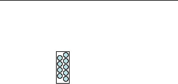
DB-9 connector with pins assigned as
shown below.
1 Carrier
Detect
(CD)
6
Data
Set
2 Received
Data
Ready
(RD)
(DSR)
3 Transmitted
7 Request
to
Data
(TD)
Send
(RTS)
4 Data
Terminal
8 Clear to
Send
Ready
(CTS)
(DTR)
9 Ring
Indicator
5 Signal
Ground
(RI)
We have
made a wire that connects
signal ground of the two
connectors,
the TD
of one to the RD of the
other and the RD of one to
the TD of the other.
This
three wire connection is
sufficient for full duplex
serial communication.
The
data on the serial port is
sent in a standard format
called RS232
communication.
The data starts with a 1 bit
called the start bit,
then five to
eight
data bits, an optional
parity bit, and one to two 0
bits called stop
bits.
The
number of data bits, parity
bits, and the number of
stop bits have to be
configured
at both ends. Also the
duration of a bit must be precisely
known
at both
ends called the baud
rate of the
communication.
The
BIOS INT 14 provides serial
port services. We will use a mix of
BIOS
services
and direct port access
for our example. A major
limitation in using
BIOS is
that it does not allows
interrupt driven data
transfer, i.e. we are
interrupted
whenever a byte is ready to be
read or a byte can be
transferred
since
the previous transmission
has completed. To achieve
this we have to
resort
to direct port access.
Important BIOS services
regarding the serial
port
are
discussed below.
INT 14 -
SERIAL - INITIALIZE PORT
AH =
00h
AL = port
parameters
DX = port number
(00h-03h)
Return:
AH = line
status
AL = modem
status
Every
bit of line status conveys
different information. From
most
significant
to least significant, the
meanings are timeout,
transmitter shift
register
empty, transmitter holding
register empty, break
detect, receiver
ready,
overrun, parity error, and
framing error. Modem status
is not used in
direct
serial communication. The
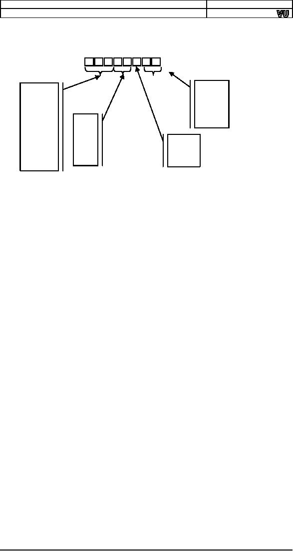
port parameters in AL consist of
the baud

Computer
Architecture & Assembly Language
Programming
Course
Code: CS401
CS401@vu.edu.pk
rate,
parity scheme, number of
stop bits, and number of
data bits. The
description
of various bits is as
under.
7
6
5
4
3
2
1
0
data
bits
baud
rate
00-5
000-110
01-6
001-150
10-7
010-300
parity
11-8
011-600
00-N
100-1200
10-N
stop
bits
101-2400
01-O
0-1
110-4800
11-E
1-2
111-9600
INT 14 -
SERIAL - WRITE CHARACTER TO
PORT
AH =
01h
AL = character to
write
DX = port number
(00h-03h)
Return:
AH bit 7 = error
flag
AH bits 6-0 = port
status
INT 14 -
SERIAL - READ CHARACTER FROM
PORT
AH =
02h
DX = port number
(00h-03h)
Return:
AH = line
status
AL = received character if AH
bit 7 clear
INT 14 -
SERIAL - GET PORT STATUS
AH =
03h
DX = port number
(00h-03h)
Return:
AH = line
status
AL = modem
status
Serial
port is also accessible via
I/O ports. COM1 is accessible
via ports
3F8-3FF
while COM2 is accessible via
2F8-2FF. The first register
at 3F8 (or
2F8
for the other port) is
the transmitter holding
register if written to and
the
receiver
buffer register if read
from. Other registers of our
interest include
3F9
whose bit 0 must be set to enable
received data available
interrupt and
bit 1 must be
set to enable transmitter
holding register empty
interrupt. Bit 0
of 3FA
is set if an interrupt is pending
and its bits 1-3
identify the cause of
the
interrupt. The three bit
causes are as
follows.
110
(16550, 82510)
timeout interrupt pending
101
(82510) timer
interrupt
100
(82510) transmit
machine
011
receiver line status interrupt.
priority=highest
010
received data available
register interrupt. priority=second
001
transmitter holding register
empty interrupt. priority=third
000
modem status
interrupt. priority=fourth
The
register at 3FB is line
control register while the
one at 3FD is line
status
register. The line status
register has the same
bits as returned in
line
status
by the get port status
BIOS interrupt however the
most significant bit
164

Computer
Architecture & Assembly Language
Programming
Course
Code: CS401
CS401@vu.edu.pk
is
reserved in this case
instead of signaling a timeout.
The register at 3FC
is
the
modem control register. Bit 3 of
this register must be set to
enable
interrupt
generation by the serial
port.
14.2.
SERIAL COMMUNICATION
We give
an example where two computers
are connected using a
serial
cable
made just as described
above. The program is to be run on
both
computers.
After that whatever is typed
on one computer appears on
the
screen
of the other.
Example
14.1
001
; a program using
serial port to transfer data back and
forth
002
[org
0x0100]
003
jmp
start
004
005
screenpos:
dw
0
; where to display
next character
006
007
; subroutine to clear the
screen
008
clrscr:
push
es
009
push
ax
010
push
cx
011
push
di
012
013
mov
ax,
0xb800
014
mov
es,
ax
;
point es to video
base
015
xor
di,
di
;
point di to top left
column
016
mov
ax,
0x0720
;
space char in
normal attribute
017
mov
cx,
2000
;
number of
screen locations
018
019
cld
; auto increment
mode
020
rep
stosw
; clear the whole
screen
021
022
pop
di
023
pop
cx
024
pop
ax
025
pop
es
026
ret
027
028
serial:
push
ax
029
push
bx
030
push
dx
031
push
es
032
033
mov
dx,
0x3FA
;
interrupt identification
register
034
in
al, dx
;
read
register
035
and
al,
0x0F
;
leave lowerniblle
only
036
cmp
al, 4
;
is receiver data
available
037
jne
skipall
;
no, leave interrupt
handler
038
039
mov
dx,
0x3F8
; data
register
040
in
al, dx
; read
character
041
042
mov
dx,
0xB800
043
mov
es, dx
; point es to video
memory
044
mov
bx, [cs:screenpos] ; get
current screen position
045
mov
[es:bx], al
; write character on
screen
046
add
word
[cs:screenpos], 2 ; update screen
position
047
cmp
word
[cs:screenpos], 4000 ; is the screen
full
048
jne
skipall
; no, leave interrupt
handler
049
050
call clrscr
; clear the
screen
051
mov
word [cs:screenpos], 0 ; reset screen
position
052
053
skipall:
mov
al,
0x20
054
out
0x20, al
; end of
interrupt
055
056
pop
es
057
pop
dx
058
pop
bx
059
pop
ax
060
iret
165

Computer
Architecture & Assembly Language
Programming
Course
Code: CS401
CS401@vu.edu.pk
061
062
start:
call clrscr
; clear the
screen
063
064
mov
ah, 0
;
initialize port
service
065
mov
al,
0xE3
;
line settings = 9600, 8, N,
1
066
xor
dx, dx
;
port = COM1
067
int
0x14
;
BIOS serial port
services
068
069
xor
ax, ax
070
mov
es, ax
; point es to IVT
base
071
mov
word [es:0x0C*4],
serial
072
mov
[es:0x0C*4+2], cs ;
hook serial port interrupt
073
074
mov
dx,
0x3FC
;
modem control
register
075
in
al,
dx
;
read
register
076
or
al,
8
;
enable bit 3
(OUT2)
077
out
dx,
al
;
write back to
register
078
079
mov
dx,
0x3F9
;
interrupt enable
register
080
in
al,
dx
;
read
register
081
or
al,
1
;
receiver data interrupt
enable
082
out
dx,
al
;
write back to
register
083
084
in
al,
0x21
; read interrupt
mask register
085
and
al,
0xEF
; enable IRQ
4
086
out
0x21, al
; write back to
register
087
088
main:
mov ah,
0
; read key
service
089
int
0x16
; BIOS
keybaord services
090
push
ax
; save key for
later use
091
092
retest:
mov
ah, 3
;
get line
status
093
xor
dx, dx
;
port = COM1
094
int
0x14
;
BIOS
keyboard services
095
and
ah, 32
;
trasmitter holding register
empty
096
jz
retest
;
no, test
again
097
098
pop
ax
; load saved
key
099
mov
dx,
0x3F8
; data port
100
out
dx, al
; send on serial
port
101
102
jmp
main
166
Table of Contents:
- Introduction to Assembly Language Programming
- Addressing Modes: Data Declaration, Direct, Register Indirect , Offset Addressing
- Branching: Comparison and Conditions, Conditional ,Unconditional Jump
- Manipulations: Multiplication Algorithm, Shifting and Rotations, Bitwise Logical Operations
- Subroutines: Program Flow, Stack, Saving and Restoring Registers
- Display Memory: ASCII Codes, Display Memory Formation, Assembly Language
- String Instructions: String Processing, Clearing Screen, String Printing, Length
- Software Interrupts: Hooking an Interrupt, BIOS and DOS Interrupts
- Real Time Interrupts and Hardware Interfacing
- Debug Interrupts: Debugger using single step interrupt, breakpoint interrupt
- Multitasking: Concept, Elaborate, Multitasking Kernel as TSR
- Video Services: BIOS Video Services, DOS Video Services
- Secondary Storage: Storage Access Using BIOS, DOS, Device Drivers
- Serial Port Programming: Serial Communication
- Protected Mode Programming: VESA Linear Frame Buffer, Interrupt Handling
- Interfacing with High Level Languages: Calling Conventions, Calling C from Assembly
- Comparison: Motorolla 68K Processors, Sun SPARC Processor