 |
Introduction:The Fundamental Problem of Communication, Program |
| << Table of Contents |
| The Fiber Optic Data Communications Link For the Premises Environment:Fiber Optic Cable >> |
Page
3 of 97
1.1
The Fundamental Problem of
Communications
The
subject of interest in this
book is premises data
communications using fiber
optic cable as the
transmission
medium. This is at once a very
specific yet very extensive
topic. It is an important
topic
both
within the context of data
communications today and into
the future. All, or almost
all, aspects of
this
subject will be explored. However, it
seems rather forbidding just
to jump into this
topic.
Rather,
it is more appropriate to take a step back to
the very beginning and talk
about the nature of
communications
first. This will allow some
needed terminology to be introduced. It
will also lead us in a
natural
way to the subject of fiber
optic cable as a transmission medium and
to why it is attractive for
premises
data links.
Of
course, the reader, well versed in data
communications, may choose to
skip past this introduction
and
suffer
no real penalty.
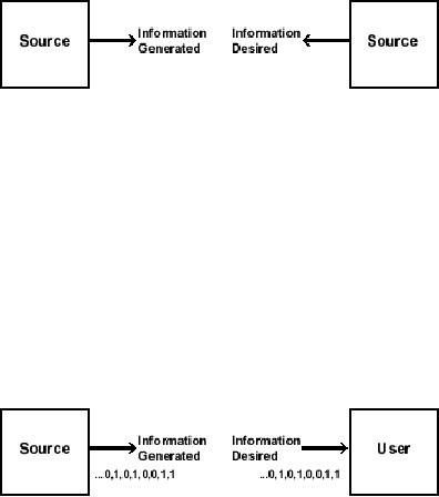
The
subject of communications really begins
with the situation shown in
Figure 1-1. Here is an
entity
called
the Source and one called the
User- located remotely from
the Source. The Source
generates
Information
and the User desires to
learn what this Information
is.
Figure
1-1: Source, User pair with
information
Examples
of this situation are
everywhere prevalent. However,
our attention will only be
focused on the
case
illustrated in Figure 1-2
where the Information is a
sequence of binary digits,
0's and 1's, bits.
Information
in this case is termed data.
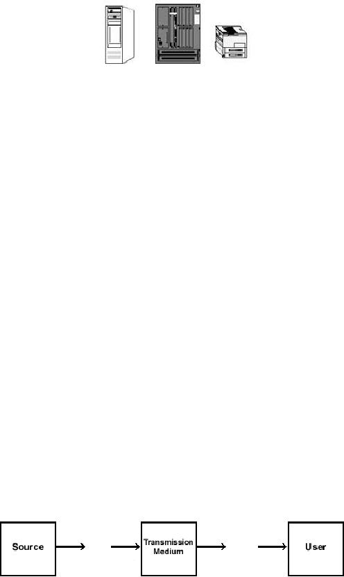
Information of this type is
generally associated with
computers,
computing
type devices and peripherals-equipment
shown in Figure 1-3.
Limiting Information to
data
presents
no real limitation. Voice, images, indeed
most other types of
Information can be processed to
look
like data by carrying
sampling and Analog-to-Digital
conversion.
Figure
1-2: Representations of
information
Page
4 of 97
Figure
1-3: Examples of sources and
users generating/desiring
"data"
It
is absolutely impossible in the
real world for the
User to obtain the
Information without the chance
of
error.
These may be caused by a variety of
deleterious effects that
shall be discussed in the
sequel.
This
means that the User
wanting to learn the
Information- the binary
sequence- must be content
in
learning
it to within a given fidelity.
The fidelity measure usually
employed is the Bit Error
Rate (BER).
This
is just the probability that
a specific generated binary
digit at the Source, a bit, is
received in error,
opposite
to what it is, at the
User.
There
are some real questions as
to how appropriate this fidelity
measure is in certain
applications.
Nonetheless,
it is so widely employed in practice, at
this point, that further
discussion is not
warranted.
The
question then arises as to
how to send the binary
data stream from Source to User. A
Transmission
Medium
is employed to transport the
Information from Source to User.
What is a Transmission
Medium?
A
Transmission Medium is some
physical entity. As shown in
Figure 1-4 it is located
between the
Source
and the User and it is accessible to
both. The Transmission
Medium has a set of
properties
described
by physical parameters. The set of
properties exists in a quiescent state.
However, at least one
of
these properties can be stressed or
disturbed at the Source end.
This is accomplished by
somehow
imparting
energy in order to stress
the property. This
disturbance does not stay
still, but affects the
parts
of
the Transmission Medium
around it. This disturbance
then travels from the Source
end to the User
end.
Consequently, energy imparted in
creating the disturbance is
thereby transferred from the
Source
end
to the User end. Finally,
this disturbance or stressed
property, can be sensed at the
User end. It can
be
measured.
Figure
1-4: Source, transmission medium,
user
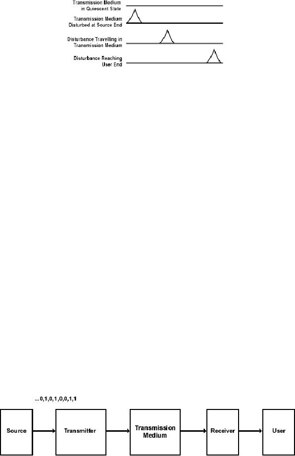
This
propagation of a disturbance by the
Transmission Medium is illustrated in
Figure 1-5.
What
are examples of transmission
media? As with types of
Information there are
many.
Page
5 of 97
Figure
1-5: Disturbance traveling in
transmission medium
The
Transmission Medium could be
air with the stressed
property being the air
pressure sound waves.
The
Transmission Medium could be an
electromagnetic field set up in
space by the current put on
an
antenna,
a radio or wireless system.
The Transmission Medium
could be a pair of electrical
conductors
with
the stressed property being
the potential difference
(the voltage) between the
conductors, an
electrical
transmission line. The
Transmission Medium could be a
sheet of writing paper with
the
stressed
property being the
light-dark pattern on the paper, a
letter. The Transmission
Medium could be
a
cylindrical glass tube with
the stressed property being
the intensity of light in
the tube, a fiber
optic
cable.
The
Source can have a disturbance to the
Transmission medium generated in
sympathy to the
Information,
that is, generate a
disturbance which varies in
time exactly as the
Information. This
encoded
disturbance will then propagate to
the User. The User can
then sense the disturbance
and decide
the
identity of the Information
that it represents. The process of
the Source generating a disturbance
in
sympathy
with the Information and
launching it into the
Transmission Medium is referred to
as
modulation
and transmission. The process of
the User sensing the
received disturbance and
deciding
what
Information it represents is referred to
as reception and demodulation. The
device that carries
out
modulation
and transmission will be called in this
work the Transmitter. The
device that carries
out
reception
and demodulation will be called the
Receiver.
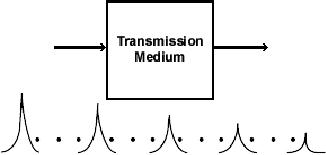
The
entire situation with data
communications then devolves to
the model illustrated in
Figure 1-6. Here
the
Source is generating bits as Information.
The User wants to learn
the identity of this
Information,
these
bits. The entities used to
get the Information from the
Source to User are the
Transmitter, the
Transmission
Medium and the Receiver. The
fundamental problem of communications is
to choose the
terminal
equipment, the Transmitter and
Receiver and to choose the
Transmission Medium so as to
satisfy
the requirements for a given
Source-User pair.
Figure
1-6: The model which
represents the fundamental
problem of communications
Page
6 of 97
The
fundamental problem of communications is
a design problem. The combination of
Transmitter,
Transmission
Medium and Receiver is termed
the communication link.
Because of the limitation
placed
on
the Information to be a sequence of
bits this combination is
generally referred to as a data
link. The
disturbance
launched into the
Transmission Medium by the
Transmitter is usually referred to as
the
input
data signal. The resulting
disturbance at the Receiver is
termed the output data
signal. In the
context
of our discussion the fundamental
problem of communications is to design a
data link
appropriate
for connecting a given
Source-User pair.
There
is no fail safe cookbook way
to solve this design problem and come up
with the best
unique
solution.
While there is science here
there is also art. There are
always alternative solutions,
each with a
particular
twist. The twist provides
some additional attractive
feature to the solution.
However, the
feature
is really peripheral to Source-User
requirements.
Most
exercises in obtaining the design
solution usually begin with
choosing a Transmission Medium
to
meet
the general requirements of
the Source-User pair. That
is, the data link design
process pivots on
choosing
the Transmission Medium.
Every Transmission Medium
has constraints on its
operation, on its
performance.
It is these constraints that
really decide which
Transmission Medium will be employed
for
the
data link design. It will be worthwhile
discussing these constraints.
1.2
The Transmission Medium- Attenuation
Constraints
Have
a Transmitter launch a disturbance
into a Transmission Medium.
Provide an input data signal
to a
Transmission
Medium. As it propagates down
the Transmission Medium to
the Receiver its
amplitude
will
decrease, getting weaker and
weaker. The disturbance, the
input data signal, is said
to suffer
attenuation.
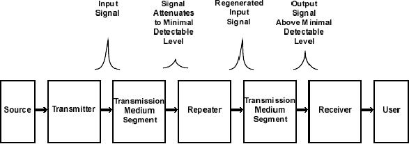
The situation is exactly as
shown in Figure 1-7.
One
immediate question that can be
raised is why does attenuation
occur? There are several
reasons. It
will
be worthwhile pointing out and
describing two of them;
spatial dispersion and loss due to
heat.
Spatial
dispersion can best be considered by
revisiting Figure 1-7. This
illustrates a one-dimensional
propagation
of the disturbance. However,
often this disturbance may
propagate in two or even
three
dimensions.
The User/Receiver may be
located in a small solid
angle relative to the
Source/Transmitter.
The
received disturbance, the
output data signal, appears
attenuated relative to the
transmitted
disturbance
because in fact, it represents
only a small fraction of the
overall energy imparted in
the
disturbance
when it was launched. This is
exactly the situation with
free space propagation of
waves
through
an electromagnetic field transmission
medium. For example, this
occurs in any sort of
radio
transmission.
Page
7 of 97
Figure
1-7: Input data signal
attenuating as it propagates down a
transmission medium
As
for loss due to heat, this
refers to the basic
interaction of the disturbance
with the material
from
which
the Transmission Medium is
comprised. As the disturbance
propagates, a portion of the
energy is
transferred
into the Transmission Medium
and heats it. For a
mechanical analogy to this
consider rolling
a
ball down a cement lane.
The ball is the disturbance
launched into the lane
that represents the
Transmission
Medium. As the ball rolls
along it encounters friction. It
loses part of its kinetic
energy to
heating
the cement lane. The
ball begins to slow down.
The disturbance gets
attenuated. This is
the
situation
with using the potential
difference between a pair of
electrical conductors as the
Transmission
Medium.
Attenuation
increases with the distance
through the Transmission
Medium. In fact, the
amplitude
attenuation
is measured in dB/km. As propagation
continues attenuation increases.
Ultimately, the
propagating
signal is attenuated until it is at
some minimal, detectable, level.
That is, the signal
is
attenuated
until it can just be sensed by
the Receiver- in the
presence of whatever interference
is
expected.
The distance at which the
signal reaches this minimal
level could be quite
significant. The
Transmission
Medium has to be able to deliver at least
the minimal detectable level of
output signal to
the
Receiver by the User. If it can
not, communications between Source and
User really can not
take
place.
There
are some tricks to getting
around this. Suppose the
disturbance has been attenuated to
the minimal
detectable
level yet it has still
not arrived at the
Receiver/User. The output
signal at this location
can
then
be regenerated. The signal can be boosted
back up to its original energy
level. It can be repeated
and
then continue to propagate on
its way to the
Receiver/User. This is shown in
Figure 1-8.
Figure
1-8: Regenerating and
repeating an attenuated signal in
order to reach the
user
Nonetheless,
the attenuation characteristics
are an item of significant consequence.
The Transmission
Medium
selected in the design must
have its attenuation
characteristics matched to the
Source-User
separation.
The lower the attenuation in
dB/km the greater advantage a
Transmission Medium
has.
1.3
The Transmission Medium - Interference
Constraints
Page
8 of 97
Have
a Transmitter launch a disturbance
into a Transmission Medium.
Provide an input data signal
to a
Transmission
Medium. As it propagates down
the Transmission Medium it will
encounter all sorts of
deleterious
effects which are termed
noise or interference. In the simplest
example, that of one person
speaking
to another person, what we refer to as
noise really is what we commonly
understand noise to
be.
What
is noise/interference? It is some
extraneous signal that is
usually generated outside of
the
Transmission
Medium. Somehow it gets
inside of the Transmission
Medium. It realizes its
effect usually
by
adding itself to the
propagating signal. Though, sometimes it
may multiply the propagating
signal.
The
term noise is generally used
when this extraneous signal
appears to have random
amplitude
parameters-
like background static in AM
radio. The term interference
is used when this
extraneous
signal
has a more deterministic
structure-like 60-cycle hum on a TV
set.
In
any case, when the
Receiver obtains the output
signal it must make its
decision about what
Information
it represents in the presence of
this noise/interference. It must
demodulate the output
signal
in
the presence of
noise/interference.
Noise/interference
may originate from a variety
of sources. Noise/interference may come
from the
signals
generated by equipment located near
the transmitter/transmission
medium/receiver. This may
be
equipment
that has nothing at all to
do with the data link.
Such equipment may be motors
or air
conditioners
or automated tools. Noise/interference
may come from atmospheric
effects. It may arise
from
using multiple electrical
grounds. Noise/interference may be
generated by active circuitry in
the
transmitter
and/or receiver. It may come
from the operation of other
data links.
In
obtaining the design solution
noise/interference makes its
effect best known through
the Bit Error
Rate
(BER). The level of
noise/interference drives the
BER. Of course, this can be countered by
having
the
Transmitter inject a stronger
input signal. It can be countered by
having the Receiver be able
to
detect
lower minimal level output
signals. But, this comes
with greater expense. It does not
hide the fact
that
there is concern with
noise/interference because of its
impact on the BER.
The
susceptibility to noise/interference
varies from Transmission
Medium to Transmission
Medium.
Consequently,
during the design process
attention has to be paid to the
Source-User pair. Attention
has
to
be directed to the application
underlying the communication
needed by this pair and to
the BER
required
by this application.
The
Transmission Medium must
then be picked that has a
noise/interference level capable of
delivering
the
required BER.
1.4
The Transmission Medium- Bandwidth
Constraints
Go
back and consider the model
illustrated in Figure 1-6.
Suppose the input signal
that the Transmitter
sends
into the Transmission Medium
is the simple cosinusoidal
signal of amplitude '1' at
frequency 'fo'
Hz.
The output signal response
to this at the Receiver is
designated 'T (fo).' Now
consider the
cosinusoidal
test input signal frequency, fo to be
varied from 0 Hz on up to �. The
resulting output
signal
as a function of frequency is T (fo) or
suppressing the subscript- it is T (f).
This is referred to as
the
transfer function of the
Transmission Medium. Generally,
the ordinate target value 'T
(f)' for a given
frequency
'f' is referred to as the
transfer function gain-
actually it is a loss- and is
expressed
logarithmically
in dB relative to the amplitude
'1' of the input
signal.
One
example transfer function is
illustrated in Figure 1-9.
This is merely an example
transfer function. It
is
not to be understood as to be typical in
any sense. It is just an
example. However, it does
illustrate a
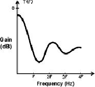
Page
9 of 97
feature
that is common in the
transfer function of any
Transmission Medium that can
actually be
obtained
in the real, physical,
world. The transfer function
rolls off with frequency.
The transfer function
shown
here oscillates, but the
maximum value of its
oscillation becomes less and
less. Yet, the
transfer
function
itself never really rolls
off and becomes dead flat
zero beyond a certain
frequency. This roll
off
with
frequency means that the
Transmission Medium attenuates the
cosinusoidal signals of the
higher
frequencies
that are given to it as
inputs. The energy of these
higher frequency signals is
somehow lost,
usually
as heat, in traversing the
Transmission Medium. The greater
the distance through
the
Transmission
Medium, the more high
frequency signals get attenuated.
This is a consequence of
the
greater
interaction between the
propagating signals and the
material comprising the
Transmission
Medium.
Figure
1-9: Example transfer
function of a transmission
medium
This
roll off feature of the
transfer function is present in every
Transmission Medium regardless of
how
it
is derived. It is present in sound waves.
It is present in conductors. It is present in fiber
optic cables. It
is
present in a phonograph record or tape.
It is even present in a sheet of writing
paper.
The
transfer function shown
rolls off with frequency.
However, most of its
activity, most of its
area,
most
of its mass, most of its
spread, seems to be below a
certain given frequency. In
this example it
looks
like the frequency 'F.'
The frequency spread of the
transfer function is referred to as
its bandwidth.
Of
course, from what was mentioned above
bandwidth decreases with the
propagation distance through
the
Transmission Medium.
Because
frequency spread is very
subjective the measure of
bandwidth is also subjective. When
you are
discussing
communications with someone and
they mention bandwidth it
isn't such a bad idea to
ask
exactly
how they are defining
it. There is a definition in
the Glossary in the back of
this book. However,
it
is only one such definition.
There are many. For
example, there is the 3 dB
bandwidth, mean square
bandwidth,
first lobe bandwidth, brick
wall bandwidth and on and on. In a
study carried out
seventeen
years
ago the author easily
identified over twenty-five
separate definitions of bandwidth. All
have
validity.
Whether one is meaningful or not
depends upon the context,
actually the application, in
which
it
is being used. One definition
may be appropriate for describing
satellite communication links
and
another
more appropriate for an FCC official
considering the request for a
broadcast AM radio
license.
In
any case, a Transmission
Medium has a transfer
function and the frequency
spread of this
transfer
function
is measured by the bandwidth.
The bandwidth parameter has
implications with respect to
the
performance
of the data link being
designed.

Page
10 of 97
In
order to see this consider
the illustration shown in
Figure 1-10. Here the Source
is generating data,
'0's
and
'1's every T seconds. Let T=
1/R, in which case the
Source is generating data at R bits per
second of
BPS.
To send this data to the
User the Transmitter is
generating either a positive or
negative impulse
every
T seconds. What is an impulse? It is an
infinitesimally narrow pulse,
but it is infinitely high so
that
it
has energy of '1.'
Now
what comes out at the
Receiver in response to the
positive impulse sent at time
zero to represent
the
binary data bit '1.' An
example result is illustrated in
Figure 1-11. Notice that
this response out of
the
Transmission
Medium to the input impulse
is a pulse spread out in
time with its center at t
seconds
where
t is not equal to 0 seconds.
This output is only an
example. It can not even be
called typical.
However,
it does indicate a property
that is typical of all
output signals received from
the Transmission
Medium.
The time spreading of the
output pulse is this common
property. It is called time
dispersion. It
is
a result of the finite
bandwidth of the Transmission
Medium. To be exact, it is due to the
fact that the
transfer
function of the Transmission
Medium- and any Transmission
Medium- attenuates the
higher
signals.
Figure
1-10: Binary data from
source represented by impulse
train put into transmission
medium by transmitter.
Impulses
are
T seconds apart.
Look
closely at the output signal
pulse shown in Figure 1-11.
Because it is spread in time it is
going to
interfere
with the output pulses due to
input data signals which
will come after it. These are
not shown in
the
illustration, but the
implication should be clear.
Likewise, these subsequent data
signals will generate
output
pulses that will also be spread in time.
Each will also interfere with the pulses
coming after it and
also
coming before it. This
type of interference is called
intersymbol interference. It is not
just a
consequence
of the input signals being
impulses. An input signal, of
finite duration, and of any
shape
will
generate an output signal
with time dispersion.
As
the data rate from the
Source increases the intersymbol
interference problem gets
worse and worse.
Output
pulses with time dispersion get
squeezed next to one another.
The growing level of
intersymbol
interference
makes it harder and harder
for the Receiver to
demodulate these
signals.
To
some extent the intersymbol
interference can be undone by sophisticated
signal processing in the
Receiver.
This usually goes under
the name of equalization. However, in
many cases equalization
still
can
not deliver the data
from the Receiver with
the BER required by the
Source-User pair. In
other
cases,
the data being generated by
the Source, say R BPS, is so high
that an equalizer can not
be
obtained
fast enough to keep up with
the output signals.

Page
11 of 97
Figure
1-11: Input signal is
positive impulse. Resulting
output signal shows time
dispersion
In
considering the data link
design task the first line of
defense against time dispersion and
intersymbol
interference
lies in the proper selection
of the Transmission Medium.
The larger the bandwidth of
the
Transmission
Medium the fewer high
frequency components will be attenuated
during propagation and
the
smaller the time dispersion.
As a result, there will be less
interference between different
output
pulses.
Make no mistake. Intersymbol
interference will not disappear. It is
just that it will be
lessened
and
made more tolerable as the
bandwidth gets larger. In
particular, to lessen intersymbol
interference
the
bandwidth of the Transmission
Medium must get larger in
relation to the Source's
generated bit rate,
R
BPS.
The
Transmission Medium must be
selected to accommodate the bit rate
generated by the Source.
This
is
a critical step in the data
link design effort. The
Transmission Medium must
have sufficient
bandwidth
so
that it will generate tolerable
intersymbol interference at the
Receiver. This means
selecting a
Transmission
Medium that has a bandwidth
that is some multiple of the
bit rate, R. A number of
rules of
thumb
are often used to do this.
However, they are too
specific and not worth
discussing at this
point
especially
since the measure of bandwidth is
subjective.
The
important point is that as
the data rate requirement, R,
goes up, this limits
the selection of
Transmission
Medium candidates. It limits the
selection to those with bandwidths
matched to it.
The
information technology explosion in
the world has made
this selection task ever
more challenging.
Continuously,
PCs are becoming more
powerful. More complex
applications programs can be run
and
are
finding their way into
easily usable software. As a result,
the Source bit rate requirement is
growing
at
an order of magnitude every
few years. To put this in
perspective, consider that
just ten years ago a
Transmission
Medium would be quite
acceptable if it had a bandwidth matched
to a Source bit rate of
9,600
BPS. This Source bit rate was
typical of that generated by
most data equipment
applications.
Today
with the growing demand for
video services and the plethora of
graphics in computer
applications
the
demand more often than not
is for a Transmission Medium
with a bandwidth matched to Source
bit
rates
well upwards of 1 MBPS,
possibly 1 GBPS.
1.5
the Transmission Medium - Cost
Constraints
You
may be able to find the
ideal Transmission Medium
relative to attenuation, interference
and
bandwidth.
But, you still may
not be able to select it as part of the
solution to the data link
design
problem.
Why? It simply costs too
much. The expense that it
presents is beyond the
budget allowed for
the
Source-User communications.
Page
12 of 97
This
isn't anything new or
revolutionary. Money doesn't drive
the world. But, it sure has
a tremendous
influence
on the ultimate choice of
solution to any problem
based in technology. This was
true one
hundred
years ago and true
today.
1.6
Attractiveness of Fiber Optic Cable As A
Premises Transmission
Medium
Considering
this discussion of the
constraints on the Transmission
Medium we are naturally led
to fiber
optic
cable as an attractive choice for
the data link design. Why?
When compared with other
candidates
for
the Transmission Medium
commonly employed today,
there is no comparison when it
comes to
attenuation,
interference and bandwidth.
Illustrations
can tell the story best
here.
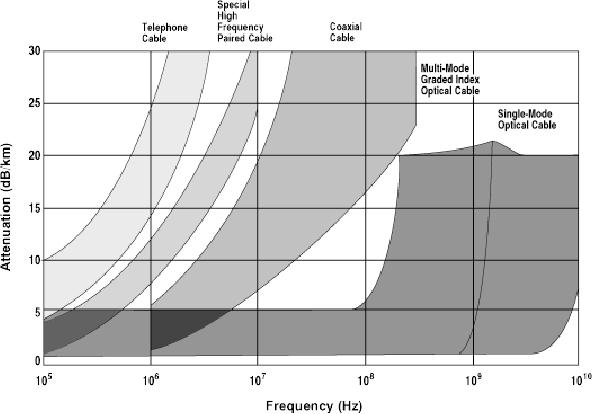
Take
a look at Figure 1-12 first.
This shows the attenuation
of several candidates for
the Transmission
Medium.
All are based on electromagnetic
technology and all are in
common use today. In other
words
none
are laboratory curiosity
items. Attenuation in dB/km is
shown as a function of frequency.
Here
frequency
would more or less refer to
the data rate from the
Source or equivalently the signaling
rate
from
the Transmitter. Attenuation of an
electromagnetic Transmission Medium
increases with
frequency
due
to effects on an atomic level,
which are well beyond
this discussion. The
attenuation curves of
different
Transmission Medium candidates
are shown as shaded strips
because the exact
attenuation
tends
to vary from sample to sample as well as
manufacturer to manufacturer. However,
the general
trend
can easily be grasped. The
attenuation of the two fiber
optic cable types, multi-mode and
single
mode,
are much, much, less
than the other candidates.
What is more their
dependence upon frequency
is
even
flat over quite a large
range. This makes designing
data links with them
simpler. You need not
be
concerned
with the change in attenuation
every time you decide to
tweak the data
rate.
To
be absolutely clear the
fiber optic cable attenuation
shown in this figure is for
fiber optic cable
fabricated
totally from glass (silica).
That is, it has a glass core
and glass cladding. There is also
fiber
optic
cable fabricated totally from
plastic and fiber optic cable
having a glass-silica core with a
plastic
cladding
(PCS- Plastic Clad Silica). It is
the pure glass- silica based
fiber optic cable that has
the low
attenuation
properties. The plastic
based fiber optic cable has
much higher attenuation,
well above
coaxial
cable. But, it does have
some attractive features
that will be discussed in a later
chapter.
Page
13 of 97
Figure
1-12: Attenuation versus frequency
(Courtesy of Siecor
Corporation)
You
get the idea. When it comes
to considering the attenuation
issue then fiber optic cable
is the
unchallenged
selection for the
Transmission Medium.
Fiber
optic cable is fabricated from
glass or plastic. Because of
the nature of this material
it allows
signals
transmitted through fiber
optic cable to be immune from
electromagnetic based forms of
noise
and
interference. This includes
power transients that may
arise from lightning
strikes. It includes noise
arising
from ground loops. In fact,
fiber optic cable provides
nearly perfect isolation
between multiple
grounds.
Noise can still affect a
fiber optic data link;
especially, if it is generated in the
receiver or
transmitter
electronic circuitry. However,
the effect of noise and interference
originating outside the
link
is
far less than with
competing choices for the
Transmission Medium, candidates
like shielded or
unshielded
twisted pair cable or coaxial cable or
free space microwave
radio.
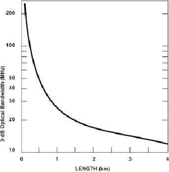
Take
a look at Figure 1-13. This
illustrates the variation of
the bandwidth of fiber optic
cable with its
length.
Remember bandwidth goes down
with increasing length. But,
that is not the concern
here. Notice
that
at up to 4 km the bandwidth is always
above 10 MHz. This implies that a
fiber optic link can
support
data rates of many 10's of
MBPS over these distances.
This can be done without having to
have
the
Transmitter resort to any sophisticated
bandwidth efficient modulation
schemes. Of course, people
talk
about fiber optic cable
being able to support Giga
Bits Per Second (1 Billion
Bits Per Second -
GBPS)
and even Tera Bits Per
Second (1 Trillion Bits Per
Second). But, remember this
depends upon
distance
and may often require
multiple repeaters.
Page
14 of 97
Figure
1-13: Bandwidth of fiber
optic cable vs. length (from
Fiber Optic Communications,
Joseph C. Palais)
To
put this in perspective,
unshielded twisted pair copper cable
over this distance can support
0-to-100
MBPS.
Coaxial cable this distance can support
about 20 MBPS. When it comes
to the bandwidth
issue
fiber
optic cable is the unquestioned
most attractive candidate for
the Transmission
Medium.
Fiber
optic cable is the unchallenged
winner in the Transmission
Medium sweepstakes when it
comes to
attenuation,
interference and bandwidth. It even
has some additional features
that are attractive
in
comparing
it to other candidates mentioned. It is
the most secure. Tampering
with fiber optic
with
transmissions
through fiber optic cable is
very difficult to do. It can be
detected far more easily
than
with
the other metallic based
candidates for Transmission
Medium let alone free
space propagation
candidates.
The small size of fiber
optic cables allows it to be placed in
ducting that is too small
for
metallic
cable. This allows room for
substantial growth in capacity if
needed. It's easier to put
more fiber
optic
cables in the same duct.
This is brought out in the
photograph provided in Figure
1-14. Finally,
fiber
optic cables do not conduct
electricity- they are glass
or plastic therefore safer.
They are
particularly
suitable for use in areas
that might have spark or
electrical hazard restrictions.
This is
especially
true of places that may
endanger the well being of a
technician working with a
long segment
of
metallic cable instead of a fiber.
Page
15 of 97
Figure
1-14: Size comparison:
coaxial cable and fiber
optic cable (Courtesy of AT&T
Archives)
Undoubtedly
now you are saying So
fiber optic cable is the
winner when it comes to
attenuation,
interference
and bandwidth. But, doesn't high cost
throw it out? Isn't it very
expensive and wasn't
this
the
ultimate driver for the
Transmission Medium selection?
It
is true when comparing fiber
optic cable to other candidates it is
not as attractive from a cost
point of
view.
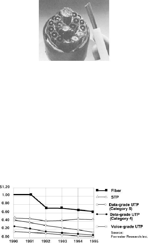
However, the situation is
getting better year by year.
In particular take a look at Figure1-15.
This
illustrates
the cost trends for
different candidates for the
Transmission Medium. Cost trends
are graphed
for
the period 1990 through
1995. Notice the decrease
for fiber optic cable. In
the years since it has
decreased
even further. Of course, this is
for glass based fiber
optic cable. Plastic fiber
optic cable has a
much
lower cost. In any case
from a cost point of view
fiber optic cable is and will probably
continue to
be
more expensive than the
cheapest, voice grade,
unshielded twisted pair cable.
However, its cost is
merging
with the other candidates.
Certainly, the really minor
cost disadvantage is greatly
outweighed
with
the significant performance
advantages.
Figure
1-15: Cost trends of common
transmission media
Putting
this altogether there is no
argument. Fiber optic cable
should be the Transmission
Medium of
choice
when considering data links
in new facilities where no
other Transmission Medium
candidate
exists.
Page
16 of 97
There
is and will continue to be tremendous
activity with respect to
carrying out data
communications in
the
wide area network or long
haul environment. This is
the environment of the long
distance carrier, the
Telephone
Company.
However,
there is even greater activity
with respect to the
implementation of data links in
the premises
or
local area environment. This
is the environment of the
office building, Small
Office Home Office
(SOHO),
the factory and the campus. As
PC's have proliferated
throughout all premise type
facilities the
need
for data communications
links has followed.
Installation of premises data
links be they
point-to-
point,
multi-point, part of a Local
Area Network (LAN) or
whatever is a major agenda
item for many
business
concerns. The case has
been made above for fiber
optic cable being the
Transmission Medium
of
choice for these links.
This is why it is the subject of
interest in this
book.
1.7
Program
This
book has been written so
that each chapter stands on
its own. There is no need to
read the chapters
in
order. There may be
occasionally cross-references from one
chapter to another. However,
the
information
can easily be gleaned without going back
to the very
beginning.
A
brief summary of the sequel is as
follows:
Chapter
2 -
A careful review is given to
the details of a fiber optic
data link for the
premise
environment.
The possibilities for and
properties of fiber optic cable
are discussed. Candidates
for the
Transmitter
and Receiver are considered. Connectors
and splices are introduced. The
performance of the
data
link is analyzed with a
careful look at the loss
budget.
Chapter
3 -
Consideration is given to exploiting
the large bandwidth
presented by fiber optic cable
to
support
the data communications of
multiple users - multiple Source -
User pairs. That is,
how to carve
out
multiple fiber optic data
links from a single fiber
optic cable in the premises
environment. This is
accomplished
by multiplexing. Both Time
Division Multiplexing (TDM) and
Wavelength Division
Multiplexing
(WDM) are discussed.
Chapter
4 -
Discussion focuses on the Local
Area Network (LAN). Fiber
optic data links are
joined
with
LAN's. Using LAN architectures carries
out a great deal of premise data
communication. The
delay
properties
of fiber optic cable can be exploited to
extend the distance coverage of a LAN. A
fiber optic
data
link can be used to connect
remote stations to a LAN hub.
Stations that may be too
far from a LAN
to
be connected by a copper cable may
possibly be joined by a fiber
optic data link.
Chapter
5 -
The manufacturing environment is
considered. In particular the environment
presented by
heavy
industry that always has a
plethora of high (electric)
powered tools in use. The
manufacturing
environment
presents a situation where
premises data communications
may have to be carried out
with
intense
noise and interference present. The
interference protection properties of a
fiber optic data
link
are
considered in this environment. In
particular, consideration is given to
the types of data links
and
networking
architectures generally found in
the manufacturing environment.
The discussion centers on
how
these links and architectures can
exploit the interference
protection properties of a fiber
optic data
link.
Table of Contents:
- Introduction:The Fundamental Problem of Communication, Program
- The Fiber Optic Data Communications Link For the Premises Environment:Fiber Optic Cable
- Exploiting The Bandwidth Of Fiber Optic Cable-Employment by Multiple Users:Sharing the Transmission Medium
- Exploiting The Delay Properties Of Fiber Optic Cable For LAN Extension:Brief History of Local Area Networks
- Exploiting The Advantages Of Fiber Optic Cable In the Industrial Environment:The Problem of Interference
- Serial Data Communications Over Fiber Optic Cable
- Standards
- Glossary