 |
WHAT IS A NETWORK |
| << E-COMMERCE |
| HOW MANY CLASS A, B, C NETWORKS AND HOSTS ARE POSSIBLE >> |
E-COMMERCE
IT430
VU
Lesson
02
WHAT IS A
NETWORK
A
network can be anything from
a simple collection of computers at
one location connected
through a
connectivity
media to the internet (a global
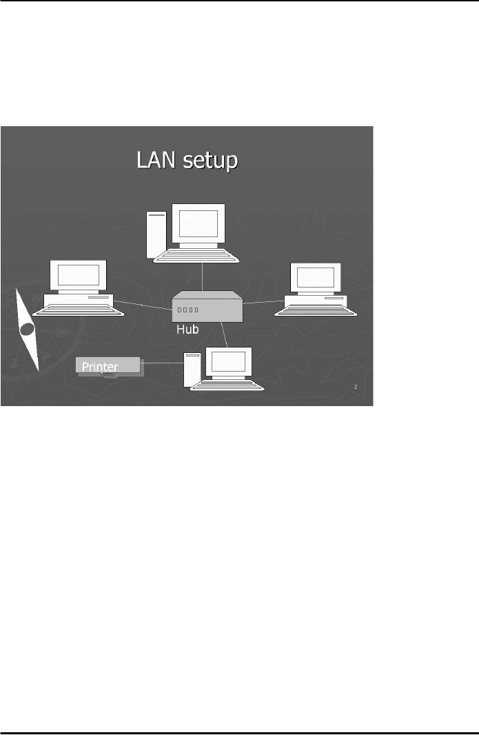
network of networks). Local Area Network
(LAN) is a server-
based
network confined to a particular
area/place. Most LANs
consist of many clients and
a few servers.
Fig.
1 below shows a simple LAN
setup:
Fig.
1
Why
networking your computer
We
network our computers to
share resources and
communicate. We can do networking
for:
1
File
sharing
2
Hardware
sharing printer sharing,
for example
3
Program
sharing
4
User
communication through a machine called
e-mail server
Network
protocol
Network
protocols are those standard
rules using which computers
on a network communicate
and
exchange
data with each other. A
group of protocols that prepare the
data for communication on the
network
is called the Protocol
stack.
International
organization for standard's (ISO)
model
In
1970's came ISO's OSI model a
conceptual model for network
communications. OSI stands
for Open
System
Interconnection Reference Model
and it proposes a 7 layer
architecture. Each layer
(except physical
layer)
at the sending machine sends instructions
through its header to the receiving
machine as to how the
accompanying
data be interpreted or treated by the
receiving machine. Header is a piece of
information
4
E-COMMERCE
IT430
VU
which
is attached to the data at its
beginning by each layer
except the physical layer.
The process of moving
the
data down the OSI Protocol
stack at the sending machine is
called Encapsulation, and the process
of
moving
the data up the OSI stack at the
receiving side is called
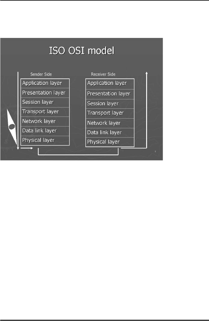
De-encapsulation. Fig. 2 below shows
names
of the 7
layers of the OSI model which
are numbered from bottom
up.
Fig.
2
Application
layer
It
sits at top of the OSI model.
Requests related to file
transfer and database
queries are handled by this
layer.
Two very important protocols, namely,
HTTP and FTP (file
transfer protocol) operate at this
layer.
Presentation
layer
It is the
translator of the OSI model. It provides instructions
through its header that
how the accompanying
data
should be formatted by the receiving machine.
MIME-multipurpose internet mail
extensions protocol
operates
at this layer to define file formats
and data types
Session
layer
It provides
instructions about the nature of communication
link between the sending and
receiving machine
during
a session. A combination of protocols
called Session Protocol Data
Units work at this layer.
Three
modes
of communication are simplex, half-duplex
and full-duplex. Simplex
means communication in one
direction
only. Half-duplex means communication in
two directions but one party
can send data at a
time.
Full-duplex
means communication in two directions
while both parties are
able to send data
simultaneously.
It
also places special
checkpoints on data packets to
trace any lost
packets.
Transport
layer
TCP
(Transmission Control Protocol) or
UDP (User Datagram Protocol)
operate at this layer. It has
two
functions. It
converts the data into data
packets. Secondly, it is responsible
for flow control of data.
TCP is
5

E-COMMERCE
IT430
VU
more
reliable as it is acknowledgment based as
opposed to UDP which does
not use any system
of
acknowledgment
for the delivery of data
packets.
Network
layer
It is
responsible for providing IP
addresses on data packets
using IP protocol. Routing
Information
Protocol
(RIP) also operates here
which enables routers to
build their routing table.
Another protocol,
Address
Resolution Protocol (ARP) is also
designed to operate at network
layer.
Data
link layer
It
places data packets into
data frames. Network
Interface Card Drivers/Protocols
operate at this layer. It is
used
to identify MAC or hardware address of
computer machines. A mathematical calculation,
Cyclical
Redundancy
Check (CRC), takes place
here to confirm integrity of
data frames.
Physical
layer
It has
got no header. All
information including the header
information is converted into binary
data at this
layer.
It results into the generation of
electric signals as 1s and 0s
are queued up and travel along
the
connectivity
media to the receiving side.
Internet
layers- TCP/IP
stack
Internet
communication model (TCP/IP Stack)
proposes a 4 layer architecture.
Following are the names
of
internet
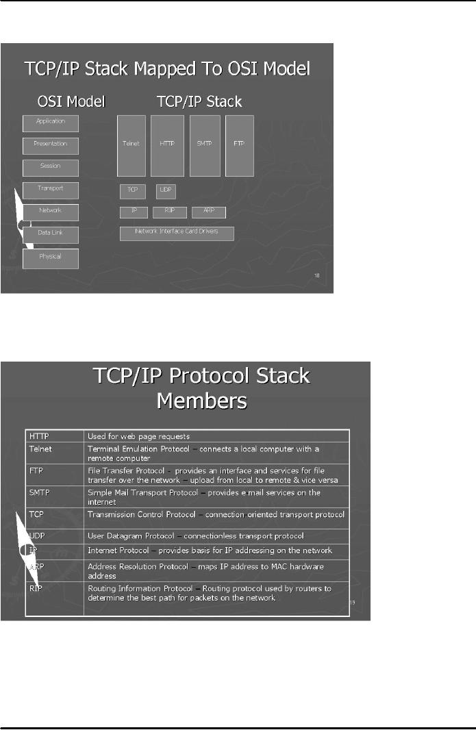
layers that map with the
OSI model's layers:
Application
layer is equivalent to OSI model's
Application, Presentation and
Session layers
Host-to-Host
Layer is equivalent to OSI model's
Transport layer
Internet
layer is equivalent to OSI model's
Network layer
Network
Access layer is equivalent to OSI
model's data link
layer
6
E-COMMERCE
IT430
VU
This
mapping of layers is also shown
in Fig. 3 below:
Fig.
3
In the
following table (Fig. 4) there is a
list of important protocols that
operate at the TCP/IP
stack.
Fig.
4
IP
addressing
It is the logical
addressing scheme used to
identify computer machines on the
internet. Each computer has
a
unique IP
address provided by IP protocol
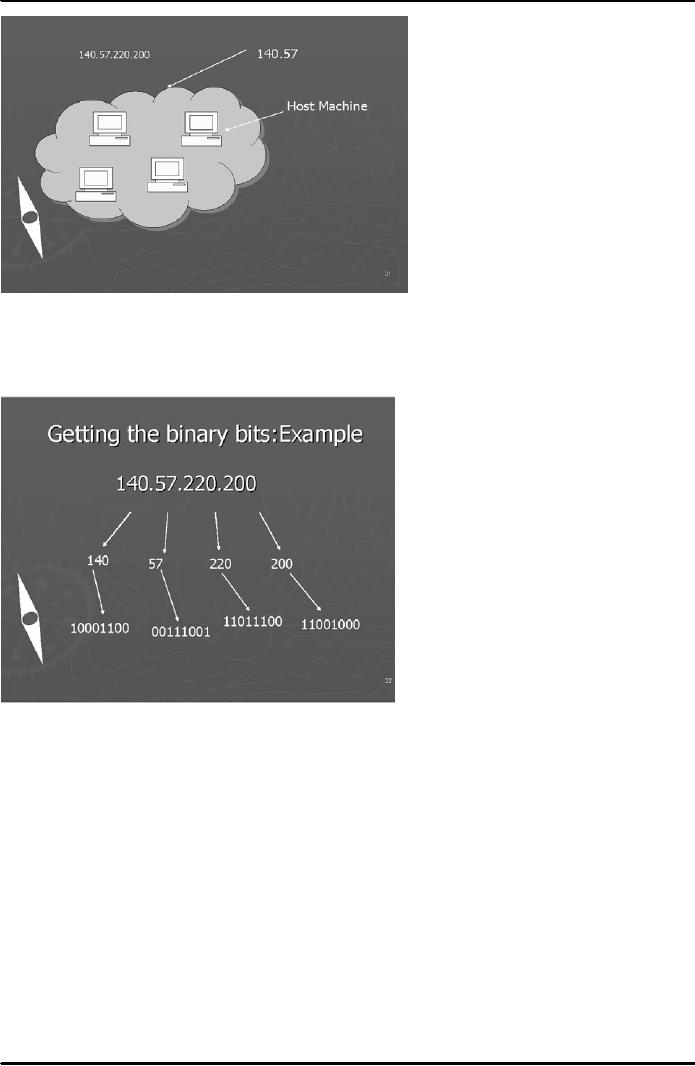
for a given session. It is represented by
four decimal numbers
separated
by a period e.g, 140.57.220.200
(see Fig. 5 below). Computers see this
information as a stream of
32
bits.
7
E-COMMERCE
IT430
VU
Fig.
5
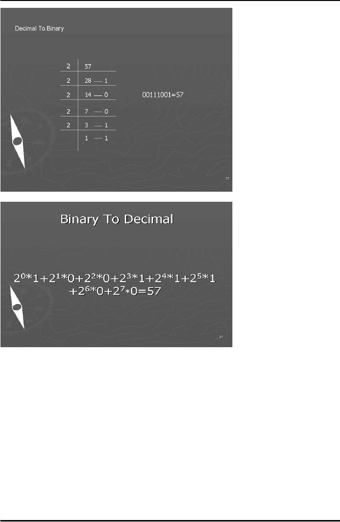
You
can look at figures 6 to 8
below to revise the basic
concept of conversion of decimal numbers
into
binary
and from binary into
decimal.
Fig.
6
8
E-COMMERCE
IT430
VU
Fig.
7
Fig.
8
Classes
of IP address
There
are five classes of IP
addresses, namely, A, B, C, D and E.
Classes A, B and C are for
general public
use,
whereas Classes D and E are
used by people belonging to certain
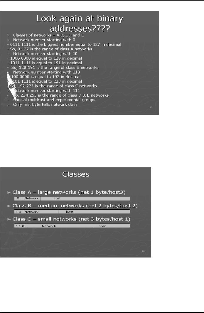
special groups. To find
which class a
particular IP
address belongs to, the rule is to
look at the number in the first byte. If
this number falls
within
the calculated range of a specific
class, then we can say
that this IP address belongs to
such particular
class.
9
E-COMMERCE
IT430
VU
Fig.
9 below explains the logic how we
can calculate these
ranges:
Fig.
9
By rule, in
class A networks first byte would refer
to the network address and the remaining
three bytes to
the
host machines on that
network providing a very large
network. In class B, the first
two bytes indicate
the
network address and the last
two bytes indicate the host
machines on that network
giving rise to a
medium-sized
network. In class C, first
three bytes refer to the network
address and the last byte to the
host
machines
on that network, which would
therefore be a very small network. (See
Fig. 10 below)
Fig.
10
10
Table of Contents:
- E-COMMERCE
- WHAT IS A NETWORK
- HOW MANY CLASS A, B, C NETWORKS AND HOSTS ARE POSSIBLE
- NETWORKING DEVICES
- BASICS OF HTML 1
- BASICS OF HTML 2
- TEXT BOXES, CHECK BOXES, RADIO BUTTONS
- FRAMES AND IMAGES IN HTML
- TAG ATTRIBUTES, SOUNDS FILES, ANIMATIONS
- STYLE SHEETS 1
- STYLE SHEETS 2
- SOME USEFUL STYLE SHEETS PROPERTIES
- JAVA SCRIPTING 1
- JAVA SCRIPTING 2
- JAVA SCRIPTING 3
- JAVA SCRIPTING AND XML
- CLIENT AND SERVER SIDE PROCESSING OF DATA
- APPLETS, CGI SCRIPTS
- MAINTAINING STATE IN A STATELESS SYSTEM
- INTEGRATION WITH ERP SYSTEMS
- FIREWALLS
- CRYPTOGRAPHY
- HASH FUNCTION AND MESSAGE DIGEST
- SYMMETRIC KEY ALGORITHMS
- VIRTUAL PIN PAYMENT SYSTEM
- E-CASH PAYMENT SYSTEM 1
- E-CASH PAYMENT SYSTEM 2
- SECURE SOCKET LAYER (SSL)
- E-BUSINESS: DISADVANTAGES OF E-BUSINESS
- E-BUSINESS REVENUE MODELS
- E-MAIL MARKETING
- CUSTOMER RELATIONSHIP MANAGEMENT (CRM)
- META INFORMATION
- DATA MINING
- CONFIDENCE AND SUPPORT
- ELECTRONIC DATA INTERCHANGE (EDI)
- PERSONAL FINANCE ONLINE
- SUPPLY CHAIN
- PORTER’S MODEL OF COMPETITIVE RIVALRY
- BARRIERS TO INTERNATIONAL E-COMMERCE
- ELECTRONIC TRANSACTIONS ORDINANCE, 2002 - 1
- ELECTRONIC TRANSACTIONS ORDINANCE, 2002 - 2
- ELECTRONIC TRANSACTIONS ORDINANCE, 2002 - 3
- GLOBAL LEGAL ISSUES OF E-COMMERCE - 1
- GLOBAL LEGAL ISSUES OF E-COMMERCE - 2