 |

Advanced Computer
Architecture-CS501
________________________________________________________
Advanced
Computer Architecture
Lecture
No. 26
Reading
Material
Vincent
P. Heuring & Harry F. Jordan
Chapter
8
Computer
Systems Design and Architecture
8.2.2
Summary
�
The
Centronic Parallel Printer
Interface(Cont.)
�
Programmed
Input/Output
�
Examples
of Programmed I/O for FALCON-A and
SRC
�
Comparisons of
FALCON-A, SRC examples
The
Centronic Parallel Printer Interface
(Cont.)
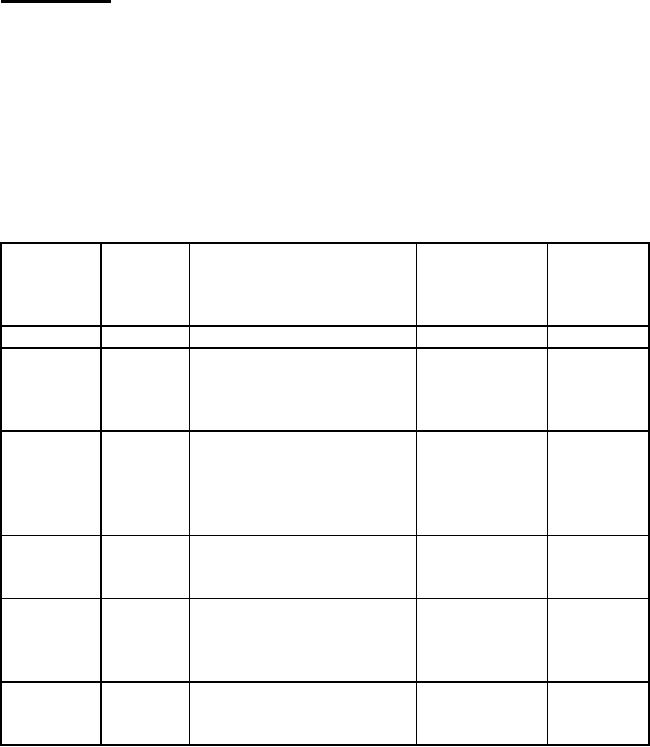
Table
1: The Centronics Parallel Printer
Interface
(power
and ground signals are not
shown)
(The
explanation of this table is
provided in lecture 25
also)
Pin#
Pin#
Signal
Direction
Function
(25-DB)
(36-DB)
Name
w.r.t.
Summary
CPU
Printer
Printer
side
side
D<7..0>
Input
8-bit
data bus
9,8,...,2
9,8,...,2
1-bit
control signal
STROBE#
Input
High:
default value.
1
1
Low:
read-in of data is
performed.
1-bit
status signal
Low:
data has been
received
ACKNLG#
Output
and the
printer is ready to
10
10
accept
new data.
High:
default value.
1-bit
status signal
BUSY
Output
Low:
default value
11
11
High:
see note#1
1-bit
status signal
PE#
Output
High:
the printer is out of
12
12
paper.
Low:
default value.
1-bit
control signal
Low:
the printer controller
is
INIT#
Input
reset to
its initial state and
16
31
Page
264
Last
Modified: 01-Nov-06

Advanced Computer
Architecture-CS501
________________________________________________________
the
print buffer is cleared.
High:
default value.
1-bit
status signal
SLCT
Output
High:
the printer is in
13
13
selected
state.
1-bit
control signal
AUTO
Input
Low:
paper is automatically
14
14
FEED
XT#
fed
after one line.
1-bit
control signal
Low:
data entry to the
SLCT
IN#
Input
printer
is possible.
17
36
High:
data entry to printer
is
not
Possible.
1-bit
status signal
ERROR#
Output
Low:
see note#2.
15
32
High:
default value.
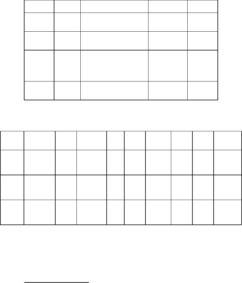
Table
2: Centronics Bit Assignment For I/O
Ports
Logical
Description
7
6
5
4
3
2
1
0
Address
0
8-bit
output
D<7>
D<6>
D<5>
D<4>
D<3>
D<2>
D<1>
D<0>
port
for
DATA
1
8-bit
input
BUSY
ACKNLG#
PE#
SLCT
ERROR#
Unused Unused
Unused
port
for
STATUS
DIR16 IRQEN
SLCT
INIT#
Auto
STROBE#
2
8-bit
output
Unused
Unused
IN#
port
for
Feed
CONTROL
XT#
16
This bit,
when set, enables the
bidirectional mode.
Page
265
Last
Modified: 01-Nov-06

Advanced Computer
Architecture-CS501
________________________________________________________
Example
# 1
Problem
statement:
Assuming
that a Centronics parallel
printer
is
interfaced to the FALCON-A
processor,
as shown
in example 3 of lecture 25,
write
an
assembly language program to
send an
80
character line to the
printer. Assume
that
the line of characters is stored in
the
memory
starting at address
1024.
Solution:
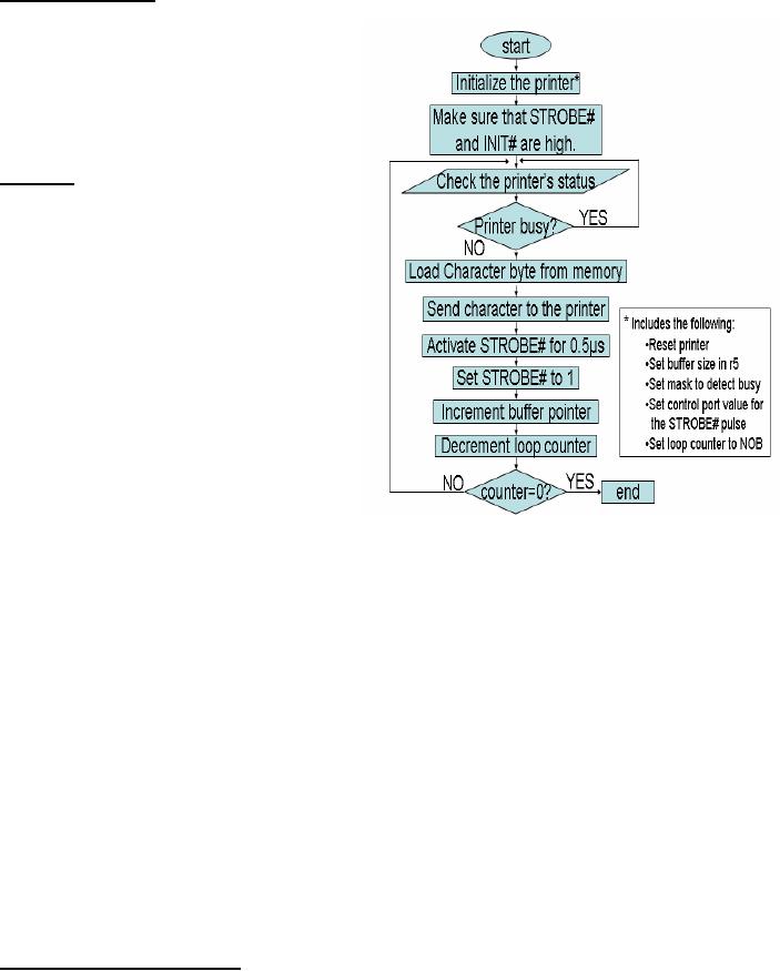
The
flowchart for the solution
is shown in
given
figure and the program
listing is
shown in
the textbox with
filename:
Example_1.
The
first thing that needs to be
done is the
initialization
of the printer. This
means
that a
"reset" command should be sent
to
the
printer. Using the
information from
Table 1,
this can be done by writing a 0 to
bit 2
(i.e., INIT#) of the control
register
having
logical address 2. In our
example,
this
maps onto address 60 of
the
FALCON-A.
(Remember to set this bit
to
logic 1
for normal operation of
the
printer).
Then we make STROBE# high
by
placing
logic 1 in bit 0 of the
control register. Bit 1 and
bit 3 should be 0 because
we
want to
activate auto line feed and
keep the printer in selected
mode. Additionally, bit
4
and bit 5
should be 0 so that interrupts
are disabled and the bi-directional mode
is not
selected.
The complete control word is
0000 0001 and this value has
been assigned to the
variable
reset in the program.
The following instruction
pair performs the
reset
operation:
movi
r1, reset
out
r1, controlp
As it is
given that the starting
address of the printer
buffer is 102417, so we place
this
address
in r5. The mask to test the
BUSY flag is placed in r3.
The value for the mask
is
80h.
This corresponds to a logic 1 in bit 7
and logic zeros elsewhere for
the status register
having
address 58 (logical address 1 in
Table 1). Then the
program enters a loop,
called
the
polling loop, to test the status of
the printer. If the printer
is busy, the loop
repeats.
The
following three instructions
form the polling
loop:
in r1,
statusp
and r1,
r1, r3
jnz
r1, [again]
17
The
mul
instruction is
used for this purpose
because the 8-bit immediate
operand in the movi
instruction
can
only be within the range
128 and +127. Using
the mul
instruction in
this way overcomes
the
limitation
of the FALCON-A. Similarly,
the shiftl
instruction is
used to bring 80h in register
r3.
Page
266
Last
Modified: 01-Nov-06
Advanced Computer
Architecture-CS501
________________________________________________________
The
status of the printer is placed in
register r1, and bit 7 is
tested for logic 0. If not
so,
the
program repeats the status
check operation.
When
the printer is ready to
accept a new character, it clears
bit 7 (i.e., the BUSY
bit) of
the
status register. At this time,
the program picks the
next character from the
memory
and sends
it to the printer. The
STROBE# line is activated and
then it is deactivated to
generate
the necessary pulse on this
input of the printer.
Finally, the buffer pointer
is
advanced,
the loop counter is decremented and
the process repeats. When
all the
characters
have been printed, the
program halts.
A number
of equates have been used in
the program to make it flexible as
well as easily
readable.
The program is shown on the
next page.
Page
267
Last
Modified: 01-Nov-06

Advanced Computer
Architecture-CS501
________________________________________________________
;
filename:
Example_1.asmfa
;
;
This
program sends an 80 character line
;
to a
FALCON-A parallel printer
;
;
Notes:
;
1. 8-bit printer
data bus connected to
;
D<7...0> of the
FALCON-A (remember big-endian)
;
Thus, the printer
actually uses addresses 57, 59 &
61
;
;
2.
one
character per 16-bits of data xfered
;
;
.org
400
;
NOB:
.equ
80
;
movi r5,
32
mul r5, r5,
r5
; r5 holds
1024 temporarily
;
movi r3,
1
shiftl r3, r3,
7
; to set
mask to 0080h
;
datap:
.equ
56
statusp:
.equ
58
controlp:
.equ
60
;
reset:
.equ
1
; used to
set unidirectional, no interrupts,
; auto line feed,
and strobe high
;
strb_H:
.equ
5
strb_L:
.equ
4
;
movi r1
reset
; use r1
for data xfer
out r1,
controlp
;
movi r7,
NOB
; use r7 as
character counter
;
again:
in r1,
statusp
;
and r1, r1,
r3
; test if BUSY =
1?
jnz r1,
[again]
; wait if BUSY =
1
;
load r1,
[r5]
out r1,
datap
movi r1,
strb_L
out r1,
controlp
movi r1,
strb_H
out r1,
controlp
addi r5, r5,
2
subi r7, r7,
1
jnz r7,
[again]
halt
Page
268
Last
Modified: 01-Nov-06

Advanced Computer
Architecture-CS501
________________________________________________________
I/O
techniques:
There
are three main techniques
using which a CPU can
exchange data with a
peripheral
device,
namely
� Programmed
I/O
� Interrupt
driven I/O
� Direct
Memory Access (DMA).
In this
section, we present the first
one.
Programmed
Input/Output
Programmed
I/O refers to the situation
when all I/O operations are
performed under the
direct
control of a program running on
the CPU. This program,
which usually consists of
a "tight
loop", controls all I/O
activity, including device status
sensing, issuing read or
write
commands, and transferring the
data18. A subsequent I/O operation
cannot begin
until
the current I/O operation to a
certain device is complete.
This causes the CPU
to
wait, and
thus makes the scheme
extremely inefficient. The
solution to Example #
3(lec24),
Example #2(lec25), and Example
#1(lec26) are examples of
programmed
input/output.
We will analyze the program
for Example #1(lec26) to
explain a few things
related
to the programmed I/O
technique.
Timing
analysis of the program in Example #
1(lec26)
The
main loop of the program
given in the solution to
Example #1(lec26) executes 80
times.
This is equal to the number
of characters to be printed on one line.
This portion of
the
program is shown again with
the execution time of each
instruction listed in brackets
with
it. The numbers shown
are for a uni-bus
movi
r7, NOB
[2]
CPU
implementation. A complete list
of
execution
times for all the
FALCON-A's ;
instructions
is given in Appendix A. A again: in
r1, statusp
[3]
and r1 ,
r1, r3
[3]
number of
things can be noted
now.
jnz
r1, [again]
[4]
1.
Assuming that the output at
the
hardware
pins changes at the end of
;
load
r1, [r5]
[5]
the
(I/O write) bus cycle,
the
out
r1, datap
[3]
STROBE#
signal will go from
logic1
movi
r1, strob_L
[2]
to logic
0 at the end of the
instruction
out
r1, controlp
[3]
pair.
movi
r1, s trob_H
[2]
out
r1, controlp
[3]
movi
r1, strb_L
[2]
addi r5,
r5, 2
[3]
out
r1, controlp
[3]
subi
r7, r7, 1
[3]
jnz
r7, [again]
[4]
halt
18
The
I/O device has no direct
access to the memory or the
CPU, and transfer is
generally done by
using
the
CPU registers.
Page
269
Last
Modified: 01-Nov-06
Advanced Computer
Architecture-CS501
________________________________________________________
The
execution time for these
two instructions is 2+3 = 5
clock periods. Therefore,
STROBE#
stays at logic1 for at least 5 clock
periods i.e., during these
two instructions.
For a
10MHz FALCON-A CPU, this
will correspond to 5x100 = 500nsec =
0.5�sec.
Since the
data to the printer is being
sent by the CPU using the
two instructions (load
r1,
[r5]
and
out
r1, datap) which
are before the first
movi
instruction,
the printer's data
setup
time requirement is satisfied as
long as we do not increase
the clock frequency
beyond
10MHz.
After
these two instructions, the
next two instructions in the
program cause STROBE#
to
go to
logic 1 again.
movi
r1, strb_H
[2]
out
r1, controlp
[3]
These two
instructions also take 5 clock periods, or
0.5�sec, to
execute. Thus, the
timing
requirement
of the STROBE# pulse width
will also be satisfied as long as we do
not
increase
the clock frequency beyond
10MHz. In case the frequency
is greater than
10MHz,
other instruction can be used in
between these two pairs of
instructions.
The
printer's data hold time
requirement is easily satisfied
because there are a number
of
instructions
after this out
instruction
which do not change the
control port, and the
character
value is already present in the
data register within the
interface since the end of
the
out
r1, datap instruction.
2. The
three instructions given
below:
again: in
r1, statusp [3]
and r1,
r1, r3 [3]
jnz
r1, [again] [4]
form
what is called a "polling
loop". The process of
periodically checking the status of
a
device to
see if it is ready for the
next I/O operation is called
"polling". It is the
simplest
way
for an I/O device to communicate
with the CPU. The
device indicates its
readiness
by
setting certain bits in a status
register, and the CPU can
read these bits to
get
information
about the device. Thus,
the CPU does all
the work and controls all
the I/O
activities.
The polling loop given above
takes 10 clock periods. For a
10MHz FALCON-
A CPU,
this is 10x100=1�sec.
One pass of the main
loop takes a total
of
3+3+4+5+3+2+3+2+3+3+3+4
= 38 clock periods which is 38x100 =
3.8�sec.
This is the
time
that the CPU takes to
send one character to the
printer. If we assume that a
1000
character
per second (cps) printer is
connected to the CPU, then
this printer has
the
capability
to print one character in every
1msec or every 1000�sec.
So, after sending a
character
in 3.8�sec to
the printer, the CPU will
wait for about 996�sec
before it can send
the
next character to the
printer. This implies that
the polling loop will be
executed about
996 times
for each character. This is
indeed a very inefficient way of
sending characters
to the
printer.
Page
270
Last
Modified: 01-Nov-06
Advanced Computer
Architecture-CS501
________________________________________________________
An
improved way of doing this
would be to include a memory of
suitable size within
the
printer.
This memory is also called a
buffer, as explained earlier.
The CPU can fill this
buffer in
a single "burst" at its own
speed, and then do something
else, while the
printer
picks up
one character at a time from
this buffer and prints it at
its own speed. This
is
exactly
the situation with today's
printers. The task of generating
the STROBE# pulse
will also be done by
the electronic circuits
within the printer. In
effect, a dedicated
processor
within the printer will do
this job. However, if the
buffer within the printer
fills
up,
the CPU will still not be
able to transfer additional data to
it. A different
handshaking
scheme
will then be needed to make the
CPU to communicate asynchronously
with the
buffer in
the printer, resulting in an
inefficient operation again. This is
explained below.
Assume
that the printer has a
FIFO type buffer of size 64
bytes that can be filled
up
without
any delay at the time
when the printer is not
printing anything. When one
or
more
character values are present in
the buffer, the printer will
pick up one value at a
time and
print it. Remember we have a
1000 cps printer, so it takes
1msec to print a
character.
The program for Example
#1(lec26) is modified for
this situation and is
given
below.
All the assumptions are the
same, unless otherwise
mentioned.
again:
in r1,
statusp [3]
and r1,
r1, r3 [3]
jnz
r1, [again] [4]
load
r1, [r5] [5]
out
r1, datap [3]
addi r5,
r5, 2 [3]
subi
r7, r7, 1 [3]
jnz
r7, [again] [4]
Note
that while the instructions
for generating the STROBE#
pulse have been
eliminated,
the
polling loop is still there.
This is necessary because
the BUSY signal will still
be
present,
although it will have a different
meaning n now. In this case,
BUSY =1 will
mean that
the buffer within the
printer is full and it can not accept
additional bytes.
The
main loop shown in the
program has an execution
time of 28 clock periods, which
is
2.8�sec
for a 10MHz FALCON-A CPU.
The polling loop still
takes 10 clock periods or
1�sec.
Assuming that this program
starts when the buffer in
the printer is empty,
the
outer
loop will execute 64 times
before the CPU encounters a
BUSY=1 condition.
After
that
the situation will be the
same as in the previous
case. The polling loop will
execute
for
about 996 times before BUSY
goes to logic 0. This
situation will persist for
the
remaining
16 characters (remember we are sending an
80 character line to the
printer).
One can
argue that the problem can be
solved by increasing the
buffer size to more
than
80 bytes.
Well, first of all, memory
is not free. So, a large
buffer will increase the cost
of
the
printer. Even if we are
willing to pay more for an
improved printer, the larger
buffer
will
still fill up whenever the
number of characters is more than
the buffer size.
When
that
happens, we will be back to square one again.
Page
271
Last
Modified: 01-Nov-06
Advanced Computer
Architecture-CS501
________________________________________________________
A careful
analysis of the situation
reveals that there is
something wrong with the
scheme
that is
being used to send data to
the printer. This problem of
having a larger overhead
of
polling
was recognized long ago, and
therefore, interrupts were
invented as an alternate
to
programmed I/O. Interrupt
driven I/O will be the topic of
the next lecture.
Programmed
I/O in SRC
In this
section, we will discuss some
more examples of programmed I/O
with our
example
processor SRC which uses the
memory mapped I/O
technique.
Program
for Character
Output
To
understand how programmed I/O
works in SRC, we will discuss a
program which
outputs
the character to the
printer. The first
instruction loads the branch
target and the
second
instruction loads the character
into lower 8 bits of
register r2. The
2-instruction
loop
reads the status register and
tests the ready signal by
checking its sign bit.
It
executes
until the ready signal
becomes logic one. On exit
from the loop, the
character is
written
to the device data register
by the store instruction.
lar
r3, wait
ldr
r2, char
wait: ld
r1, COSTAT
brpl
r3, r1
st r2,
COUT
A 10
MIPS, SRC would execute 10,000
instructions waiting for a
1,000 character/sec
printer.
Program
Fragment to Print 80-Character
Line
The
next example for the SRC is
of a program which sends an
80-character line to a
line
printer
with a command register.
There are two nested
loops starting at label
wait. The
two
instruction inner loop,
which waits for ready and
the outer seven instruction
loop
which
performs the following
tasks.
� Outputs
a character
� Advance
the buffer pointer
� Decrement
the register containing the
number of characters left to
print
� Repeat
if there are more characters
left to send.
The
last two instructions issue
the command to print the
line.
The
next example discussed from
the book is of a driver
program for 32-character
input
devices
(Figure 8.10, Page
388).
Comparisons
of the SRC and FALCON-A
Examples
The
FALCON-A and SRC programmed I/O examples
discussed are similar with
some
differences.
In the first example
discussed for the SRC (i.e.
Character output), the
control
signal
responsible for data
transfer by the CPU is the
ready signal while for
FALCON-A
Busy
(active low)signal is checked. In the
second example for the
SRC, the instruction
set,
address width and no. of
lines on address is
different.
Although
different techniques have
been used to increase the
efficiency of the
programmed
I/O, overheads due to polling can not be
completely eliminated.
Page
272
Last
Modified: 01-Nov-06
Table of Contents:
- Computer Architecture, Organization and Design
- Foundations of Computer Architecture, RISC and CISC
- Measures of Performance SRC Features and Instruction Formats
- ISA, Instruction Formats, Coding and Hand Assembly
- Reverse Assembly, SRC in the form of RTL
- RTL to Describe the SRC, Register Transfer using Digital Logic Circuits
- Thinking Process for ISA Design
- Introduction to the ISA of the FALCON-A and Examples
- Behavioral Register Transfer Language for FALCON-A, The EAGLE
- The FALCON-E, Instruction Set Architecture Comparison
- CISC microprocessor:The Motorola MC68000, RISC Architecture:The SPARC
- Design Process, Uni-Bus implementation for the SRC, Structural RTL for the SRC instructions
- Structural RTL Description of the SRC and FALCON-A
- External FALCON-A CPU Interface
- Logic Design for the Uni-bus SRC, Control Signals Generation in SRC
- Control Unit, 2-Bus Implementation of the SRC Data Path
- 3-bus implementation for the SRC, Machine Exceptions, Reset
- SRC Exception Processing Mechanism, Pipelining, Pipeline Design
- Adapting SRC instructions for Pipelined, Control Signals
- SRC, RTL, Data Dependence Distance, Forwarding, Compiler Solution to Hazards
- Data Forwarding Hardware, Superscalar, VLIW Architecture
- Microprogramming, General Microcoded Controller, Horizontal and Vertical Schemes
- I/O Subsystems, Components, Memory Mapped vs Isolated, Serial and Parallel Transfers
- Designing Parallel Input Output Ports, SAD, NUXI, Address Decoder , Delay Interval
- Designing a Parallel Input Port, Memory Mapped Input Output Ports, wrap around, Data Bus Multiplexing
- Programmed Input Output for FALCON-A and SRC
- Programmed Input Output Driver for SRC, Input Output
- Comparison of Interrupt driven Input Output and Polling
- Preparing source files for FALSIM, FALCON-A assembly language techniques
- Nested Interrupts, Interrupt Mask, DMA
- Direct Memory Access - DMA
- Semiconductor Memory vs Hard Disk, Mechanical Delays and Flash Memory
- Hard Drive Technologies
- Arithmetic Logic Shift Unit - ALSU, Radix Conversion, Fixed Point Numbers
- Overflow, Implementations of the adder, Unsigned and Signed Multiplication
- NxN Crossbar Design for Barrel Rotator, IEEE Floating-Point, Addition, Subtraction, Multiplication, Division
- CPU to Memory Interface, Static RAM, One two Dimensional Memory Cells, Matrix and Tree Decoders
- Memory Modules, Read Only Memory, ROM, Cache
- Cache Organization and Functions, Cache Controller Logic, Cache Strategies
- Virtual Memory Organization
- DRAM, Pipelining, Pre-charging and Parallelism, Hit Rate and Miss Rate, Access Time, Cache
- Performance of I/O Subsystems, Server Utilization, Asynchronous I/O and operating system
- Difference between distributed computing and computer networks
- Physical Media, Shared Medium, Switched Medium, Network Topologies, Seven-layer OSI Model