 |

Advanced Computer
Architecture-CS501
Advanced
Computer Architecture
Lecture
No. 22
Reading
Material
Vincent
P. Heuring&Harry F. Jordan
Chapter
5
Computer
Systems Design and Architecture
5.3
Summary
�
Microprogramming
�
Working
of a General Microcoded
Controller
�
Microprogram
Memory
�
Generating
Microcode for Some Sample
Instructions
�
Horizontal
and Vertical Microcode
Schemes
�
Microcoded
1-bus SRC Design
�
The SRC
Microcontroller
Microprogramming
In the
previous lectures, we have
discussed how to implement
logic circuitry for a
control
unit
based on logic gates. Such
an implementation is called a hardwired
control unit. In a
micro
programmed control unit,
control signals which need
to be generated at a certain
time
are stored together in a control
word. This control word is
called a microinstruction.
A
collection of microinstructions is called
a microprogram. These
microprograms
generate
the sequence of necessary
control signals required to
process an instruction.
These
microprograms are stored in a memory
called the control
store.
As
described above microprogramming or
microcoding is an alternative way to
design
the
control unit. The microcoded
control unit is itself a
small stored program
computer
consisting
of
Micro-PC
Microprogram
memory
Microinstruction
word
Comparison
of hardwired and microcoded control
unit
Hardwired
Control Unit
Microcoded
Control Unit
The
relationship between control
The control signals here are
stored as words
inputs
and control outputs is a series in a
microcode memory.
of
Boolean functions.
Hardwired
control units are generally
Microcode units simplify the
computer logic
faster.
but it is
comparatively slower.
Page
224
Last
Modified: 01-Nov-06
Advanced Computer
Architecture-CS501
Working
of a general microcoded
controller
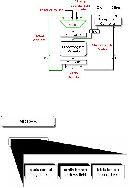
A
microcoded controller works in
the same way as a small
general purpose computer.
1. Fetch
a micro-instruction and increment
micro-PC.
2.
Execute the instruction present in
micro-IR.
3. Fetch
the next instruction and so
on...
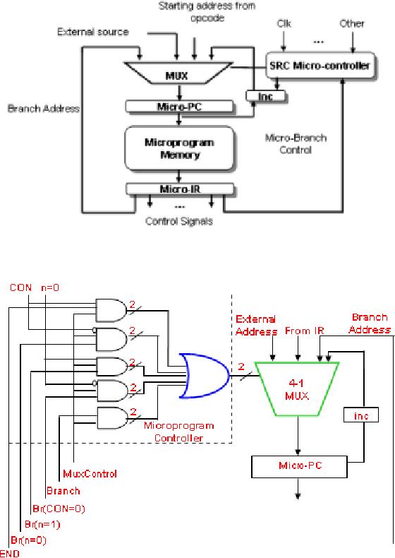
The
microcoded control unit is
like
a small
computer in itself. It
consists
of
a
microprogram
memory,
which is read using a
micro
program counter. The
micro
PC
is
controlled
by
the
microprogram
controller. Values of
the
micro PC depends on a 4 to 1
MUX. The
source may be the
incremented
micro PC value, or a
calculated
branch value, or a
value
derived
by decoding an opcode
for
an
instruction. The
microprogram
memory
writes the control word
at
the
chosen address into the
micro
instruction
register. This control word
is basically the set of all
the control signals
needed
to
execute the instruction at
that particular
instant.
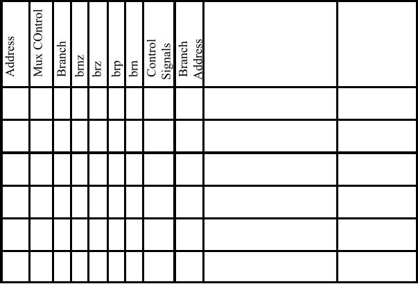
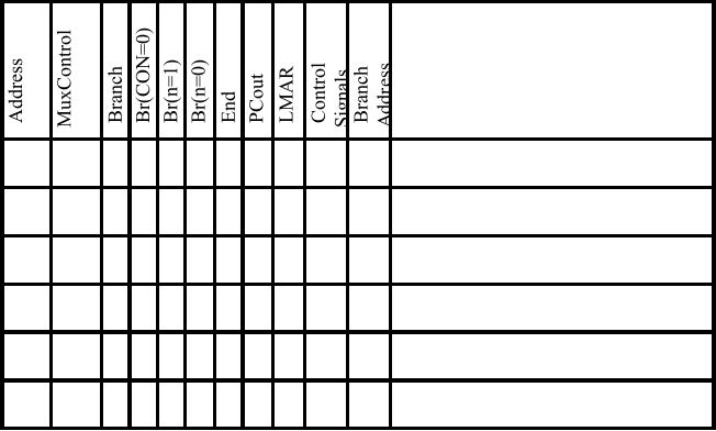
Fields in the
micro instruction
C
Bits
These
form the control
signal
field
M
Bits
These
form the branch
address
field
B
Bits
These
form the branch
control
field.
Loading
the micro-PC
The
micro-PC can be loaded from one of the
four possible sources
� Simple
increment Steps
sequentially from microinstruction to
microinstruction
� Lookup
table A lookup
table maps the opcode
field to the starting
address of the
microcode
routine that generates
control signals.
Page
225
Last
Modified: 01-Nov-06
Advanced Computer
Architecture-CS501
� External
source Initializes
micro-PC to begin an operation e.g.
interrupts service,
reset
etc.
� Branch
addresses Jumps
anywhere in the microprogram
memory on the basis
of
conditional
or unconditional branch.
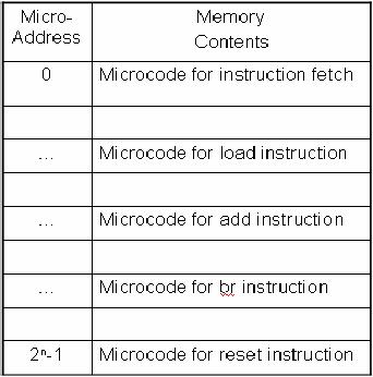
Microprogram
Memory
�
This
small memory contains
microroutines for all the
instructions in the
ISA
�
The
micro-PC supplies the
address and it returns the
control word stored at
that
address
�
It is
much faster and smaller than
a typical main memory
Layout
of a typical microprogram
memory
Generating
Microcode for Some Sample
Instructions
� The
control word for an
instruction is used to generate
the equivalent
microcode
sequence
� Each
step in RTL corresponds to a microinstruction
executed to generate the
control
signals.
Each bit
in the control words in the
microprogram memory represents a
control signal.
The
value of that bit decides
whether the signal is to be
activated or not.
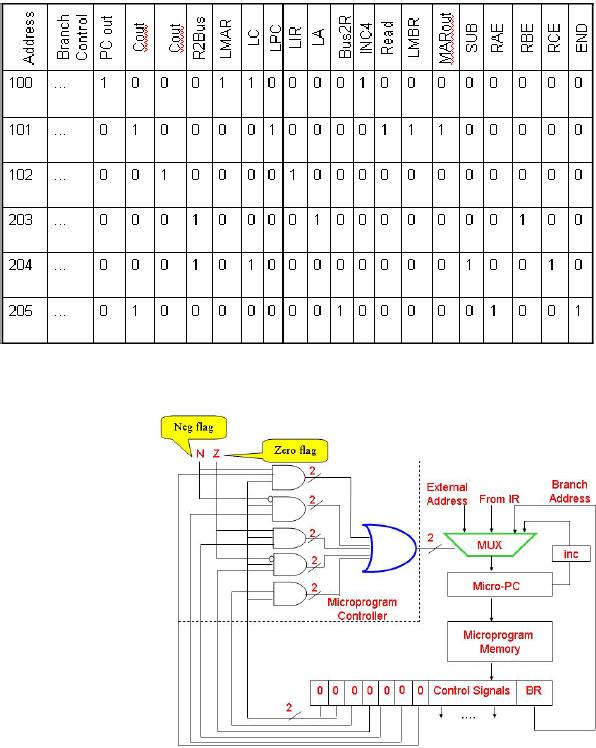
Example:
Control Signals for the sub
Instruction
The
first three addresses from
100 to 102 represent microcode for
instruction fetch and
the
last three addresses from
203 to 205 represent microcode for sub
instruction. In the
first
cycle at address 100, the
control signal PCout, LMAR,
LC, and INC4 are
activated
and all
other signals are
deactivated. All these control
signals are for the SRC
processor.
Page
226
Last
Modified: 01-Nov-06
Advanced Computer
Architecture-CS501
So, if
the micro-PC contains 100,
the contents of microprogram
memory are copied
into
the
micro IR. This corresponds to the
structural RTL description of the T0
clock during
instruction
fetch phase. In the same
way, the content of address
101 corresponds to T1,
and the
content of address 102 corresponds to
T2.
Microprogram
Controller functions: Branching and
looping
�
Microprogram controller
controls
the sequence of
the
flow
of
microinstructions.
� The
inputs to the
microcontroller
are from
the
branch control fields
specified
in the microcode
word.
� Its
output controls the 4
to 1
multiplexer inside
the
microcoded
control unit.
�
It
implements
conditional
execution and
both
conditional
and
unconditional
branch
If a
branch instruction is encountered
within the microprogram
hardwired logic
selects
the
branch address as the source of
micro-PC using 4 to 1 mux.
This hardwired logic
caters
for all branch instructions
including branch if
zero.
Page
227
Last
Modified: 01-Nov-06
Advanced Computer
Architecture-CS501
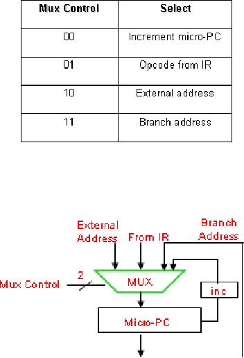
4-1
Multiplexer
The
multiplexer supplies one of the
four possible values to the
micro-PC
The
incremented value of the
micro-PC is used when
dealing with the normal
flow of
microinstructions.
The
opcode from the instruction
is used to set the micro-PC
when a microroutine is
initially
being loaded.
External
address is used when it is
required to reset the
microprogram controller.
Branch
address is set into the
micro-PC when a branch
microinstruction is encountered.
Page
228
Last
Modified: 01-Nov-06
Advanced
Computer Architecture
Lecture
22
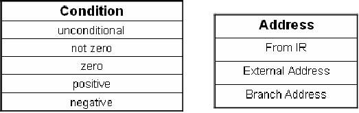
How
to form a branch
� A
branch can be implemented by choosing one
alternative from each of the
following
two
lists.
� This
scheme provides flexibility in
choosing branches as we can form any
combination
of
conditions and addresses.
Page
229
Last
Modified: 01-Nov-06
Advanced Computer
Architecture-CS501
________________________________________________________
Microcode
Branching Examples
Following
is an example of branch instructions in
microcode
Branching
Equivalent
Action
C
construct
400 00 0 0
0
00...
xxx No
branch,goto next
{...};
address
in sequence-401
401 01 1 0
0
00...
xxx To
the address supplied
{...};
goto
by
opcode
initial
address;
402 10 0 0
1
00...
xxx To
external address if Z {...}; if Z
then
flag is
set
goto
Ext. Add.
403 11 0 0
0
01...
200 To 200 if N
flag is set, {...}; if N
then
else to
404
goto
Label1;
404 11 0 0
0
1 0
000
406 To 406 if N is
false, else While
(N)
to
405
{...};
405 11 1 0
0
00...
404
Branch to 404
While
contd...
Similarity
between microcode and high level
programs
� Any
high level construct such as
if-else, while, repeat etc.
can be implemented using
microcode
� A
variety of microcode compilers
similar to the high level
compilers are available
that
allow
easier programming in
microcode
� This
similarity between high
level language and microcode
simplifies the task of
controller
design.
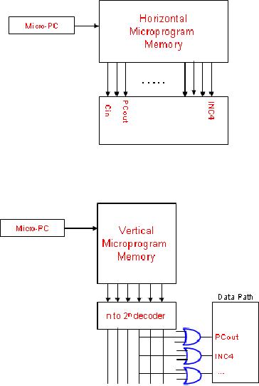
Horizontal
and vertical microcode
schemes
In
horizontal microcode schemes,
there are no intermediate
decoders and the
control
word
bits are directly connected
to their destination i.e.
each bit in the control
word is
directly
connected to some control
signal and the total number
of bits in the control
word
is equal
to the total number of
control signals in the
CPU.
Vertical
microcode schemes employ an
extra level of decoding to reduce
the control
word
width. From an n bit control
word we may have 2n bit signal
values.
Page
230
Last
Modified: 01-Nov-06
Advanced Computer
Architecture-CS501
________________________________________________________
However,
a completely vertical scheme is
not feasible because of the
high degree of fan
out.
Horizontal
Microcode Scheme
Vertical
Microcode Scheme
Microcoded
1-bus SRC design
In the
SRC the bits from the
opcode in the instruction
register are decoded to
fetch the
address
of the suitable microroutine
from the microprogram
memory. The
microprogram
controller
for the SRC microcoded
control unit employs the
logic for handling
exceptions
and reset
process. Since the SRC does
not have any condition
codes, we use the CON
and
n signals
instead of N and Z flags to control branches in
case of branch if equal to
zero or
branch if
less than
instructions.
The
SRC Microprogram
Controller
Page
231
Last
Modified: 01-Nov-06
Advanced Computer
Architecture-CS501
________________________________________________________
� The
microprogram controller for
the SRC microcoded control
unit employs the
logic
for
handling exceptions and reset
process
� Since
the SRC does not have
any condition codes, we use
the CON and n signals
instead of N and Z
flags to control branches
Page
232
Last
Modified: 01-Nov-06
Advanced Computer
Architecture-CS501
________________________________________________________
Microcode
for some SRC
instructions
RTL
300
00
0000
01
1
...
xxx
MAR
PC:
C
PC +
4;
301
00
0000
00
0
...
xxx
MBR
M[MAR]:
PC
C;
xxx
IR,Micro-PC MBR<31...27>;
302
01
1000
00
0
...
400
00
0000
00
0
...
xxx
A
R[rb];
401
00
0000
00
0
...
xxx
C
A +
R[rc];
402
11
1000
10
0
...
300
R[ra]
C;
Micro-PC
300;
Assume
the first control word at
address 300. The RTL of this
instruction is MAR
PC
combined
with C PC+4. To
facilitate these actions the
PCout signal bit and the
LMAR
signal
bit are set to one, so
that the value of the PC
may be written to the
internal
processor
bus and written onto the MAR.
The instructions at 300, 301 and 302
form the
microcode
for instructions fetch. If we
examine the RTL we can see
all the functionality
of the
fetch instruction. The value
of PC is incremented, the old
value of PC is sent to
memory,
the instruction from the
sent address is loaded into memory
buffer register.
Then
the opcode of the fetched
instruction is used to invoke
the appropriate microroutine.
Alternative
approaches to microcoding
�
Bit
ORing
�
Nanocoding
�
Writable
Microprogram Memory
�
Subroutines
in Microprogramming
Page
233
Last
Modified: 01-Nov-06
Table of Contents:
- Computer Architecture, Organization and Design
- Foundations of Computer Architecture, RISC and CISC
- Measures of Performance SRC Features and Instruction Formats
- ISA, Instruction Formats, Coding and Hand Assembly
- Reverse Assembly, SRC in the form of RTL
- RTL to Describe the SRC, Register Transfer using Digital Logic Circuits
- Thinking Process for ISA Design
- Introduction to the ISA of the FALCON-A and Examples
- Behavioral Register Transfer Language for FALCON-A, The EAGLE
- The FALCON-E, Instruction Set Architecture Comparison
- CISC microprocessor:The Motorola MC68000, RISC Architecture:The SPARC
- Design Process, Uni-Bus implementation for the SRC, Structural RTL for the SRC instructions
- Structural RTL Description of the SRC and FALCON-A
- External FALCON-A CPU Interface
- Logic Design for the Uni-bus SRC, Control Signals Generation in SRC
- Control Unit, 2-Bus Implementation of the SRC Data Path
- 3-bus implementation for the SRC, Machine Exceptions, Reset
- SRC Exception Processing Mechanism, Pipelining, Pipeline Design
- Adapting SRC instructions for Pipelined, Control Signals
- SRC, RTL, Data Dependence Distance, Forwarding, Compiler Solution to Hazards
- Data Forwarding Hardware, Superscalar, VLIW Architecture
- Microprogramming, General Microcoded Controller, Horizontal and Vertical Schemes
- I/O Subsystems, Components, Memory Mapped vs Isolated, Serial and Parallel Transfers
- Designing Parallel Input Output Ports, SAD, NUXI, Address Decoder , Delay Interval
- Designing a Parallel Input Port, Memory Mapped Input Output Ports, wrap around, Data Bus Multiplexing
- Programmed Input Output for FALCON-A and SRC
- Programmed Input Output Driver for SRC, Input Output
- Comparison of Interrupt driven Input Output and Polling
- Preparing source files for FALSIM, FALCON-A assembly language techniques
- Nested Interrupts, Interrupt Mask, DMA
- Direct Memory Access - DMA
- Semiconductor Memory vs Hard Disk, Mechanical Delays and Flash Memory
- Hard Drive Technologies
- Arithmetic Logic Shift Unit - ALSU, Radix Conversion, Fixed Point Numbers
- Overflow, Implementations of the adder, Unsigned and Signed Multiplication
- NxN Crossbar Design for Barrel Rotator, IEEE Floating-Point, Addition, Subtraction, Multiplication, Division
- CPU to Memory Interface, Static RAM, One two Dimensional Memory Cells, Matrix and Tree Decoders
- Memory Modules, Read Only Memory, ROM, Cache
- Cache Organization and Functions, Cache Controller Logic, Cache Strategies
- Virtual Memory Organization
- DRAM, Pipelining, Pre-charging and Parallelism, Hit Rate and Miss Rate, Access Time, Cache
- Performance of I/O Subsystems, Server Utilization, Asynchronous I/O and operating system
- Difference between distributed computing and computer networks
- Physical Media, Shared Medium, Switched Medium, Network Topologies, Seven-layer OSI Model