 |
Foundations of Computer Architecture, RISC and CISC |
| << Computer Architecture, Organization and Design |
| Measures of Performance SRC Features and Instruction Formats >> |
Advanced Computer
Architecture-CS501
Lecture
Handout
Computer
Architecture
Lecture
No. 2
Reading
Material
Vincent
P. Heuring&Harry F. Jordan
Chapter
2,Chapter3
Computer
Systems Design and Architecture
2.1,
2.2, 3.2
Summary
1)
A
taxonomy of computers and their
instructions
2)
Instruction
set features
3)
Addressing
modes
4)
RISC and
CISC architectures
Foundations
Of Computer Architecture
TAXONOMY
OF COMPUTERS AND THEIR
INSTRUCTIONS
Processors
can be classified on the basis of
their instruction set
architectures. The
instruction
set architecture, described in
the previous module gives us
a `programmer's
view' of
the machine. This module
discussed a number of topics
related to the
classifications
of computers and their
instructions.
CLASSES OF
INSTRUCTION SET
ARCHITECTURE:
The
mechanism used by the CPU to
store instructions and data can be used
to classify the
ISA
(Instruction Set Architecture).
There are three types of
machines based on
this
classification.
�
Accumulator based
machines
� Stack
based machines
�
General purpose register (GPR)
machines
ACCUMULATOR
BASED MACHINES
Accumulator
based machines use special registers
called the accumulators to
hold one
source operand and
also the result of the
arithmetic or logic operations
performed. Thus
the
accumulator registers collect (or
`accumulate') data. Since the
accumulator holds one
of the
operands, one more register may be
required to hold the address
of another
operand.
The accumulator is not used
to hold an address. So accumulator
based machines
are also
called 1-address machines.
Accumulator machines employ a
very small number
Page
30
Last
Modified: 01-Nov-06
Advanced Computer
Architecture-CS501
of
accumulator registers, generally only
one. These machines were
useful at the time
when
memory was quite expensive; as
they used one register to
hold the source operand
as well
as the result of the
operation. However, now that
the memory is
relatively
inexpensive,
these are not considered
very useful, and their use
is severely limited for
the
computation
of expressions with many operands.
STACK
BASED MACHINES
A stack is a
group of registers organized as a
last-in-first-out (LIFO) structure. In
such a
structure,
the operands stored first,
through the push operation,
can only be accessed
last,
through a
pop operation; the order of
access to the operands is reverse of
the storage
operation.
An analogy of the stack is a
"plate-dispenser" found in several
self-service
cafeterias.
Arithmetic and logic operations
successively pick operands
from the top-of-
the-stack
(TOS), and push the results
on the TOS at the end of the
operation. In stack
based
machines, operand addresses need
not be specified during the
arithmetic or logical
operations.
Therefore, these machines
are also called 0-address
machines.
GENERAL-PURPOSE-REGISTER
MACHINES
In
general purpose register machines, a
number of registers are available
within the CPU.
These registers do
not have dedicated
functions, and can be employed for a
variety of
purposes. To
identify the register within
an instruction, a small number of
bits are
required
in an instruction word. For
example, to identify one of the 64
registers of the
CPU, a
6-bit field is required in
the instruction.
CPU
registers are faster than
cache memory. Registers are also
easily and more
effectively
used by the compiler compared to
other forms of internal storage.
Registers
can also be
used to hold variables,
thereby reducing memory
traffic. This increases
the
execution
speed and reduces code size
(fewer bits required to code
register names
compared to
memory) .In addition to data, registers
can also hold addresses and
pointers
(i.e.,
the address of an address).
This increases the
flexibility available to
the
programmer.
A number
of dedicated, or special purpose registers are also
available in general-purpose
machines,
but many of them are
not available to the
programmer. Examples of
transparent
registers include the stack pointer,
the program counter, memory
address
register,
memory data register and
condition codes (or flags)
register, etc.
We should
understand that in reality,
most machines are a
combination of these
machine
types.
Accumulator machines have
the advantage of being more
efficient as these can
store
intermediate results of an operation
within the CPU.
INSTRUCTION
SET
An
instruction set is a collection of
all possible machine language
commands that are
understood
and can be executed by a processor.
ESSENTIAL
ELEMENTS OF COMPUTER
INSTRUCTIONS:
There
are four essential elements of an
instruction; the type of
operation to be performed,
the place
to find the source operand(s),
the place to store the result(s) and
the source of
the
next instruction to be executed by
the processor.
Type
of operation
In module
1, we described three ways to
list the instruction set of
a machine; one way of
enlisting
the instruction set is by
grouping the instructions in
accordance with the
functions
they perform. The type of
operation that is to be performed can be
encoded in
Page
31
Last
Modified: 01-Nov-06
Advanced Computer
Architecture-CS501
the
op-code (or the operation code)
field of the machine
language instruction.
Examples
of
operations are mov, jmp,
add; these are the assembly
mnemonics, and should not
be
confused
with op-codes. Op-codes are simply
bit-patterns in the machine
language format
of an
instruction.
Place
to find source
operands
An
instruction needs to specify
the place from where the
source operands will be
retrieved
and used. Possible locations of
the source operands are CPU
registers, memory
cells and
I/O locations. The source operands can
also be part of an instruction itself;
such
operands
are called immediate
operands.
Place
to store the results
An
instruction also specifies the location
in which the result of the
operation, specified by
the
instruction, is to be stored. Possible
locations are CPU registers,
memory cells and
I/O
locations.
Source
of the next instruction
By
default, in a program the
next instruction in sequence is
executed. So in cases
where
the
next-in-sequence instruction execution is
desired, the place of next instruction
need
not be
encoded within the
instruction, as it is implicit. However,
in case of a branch,
this
information
needs to be encoded in the
instruction. A branch may be
conditional or
unconditional,
a subroutine call, as well as a
call to an interrupt service
routine.
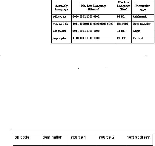
Example
The
table provides examples of
assembly language commands and
their machine
language
equivalents. In the
instruction
add
cx, dx, the contents of
the location
dx are
added to the contents of
the
location
cx, and the result is stored
in
cx.
The instruction type is
arithmetic,
and the
op-code for the add
instruction
is 0000,
as shown in this
example.
CLASSIFICATIONS
OF
INSTRUCTIONS:
We can
classify instructions according to
the format shown
below.
�
4-address instructions
�
3-address instructions
�
2-address instructions
�
1-address instructions
�
0-address instructions
The
distinction is based on the
fact that some operands
are accessed from memory,
and
therefore
require a memory address,
while others may be in the
registers within the
CPU
or they
are specified
implicitly.
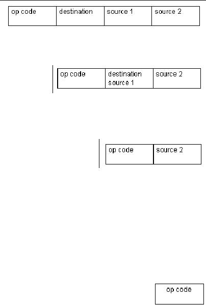
4-address
instructions
The
four address instructions
specify the addresses of two
source operands, the address of
the
destination operand and the next
instruction address.
4-address
instructions
are not
very
common
because
the next
Page
32
Last
Modified: 01-Nov-06
Advanced Computer
Architecture-CS501
instruction
to be executed is sequentially stored
next to the current
instruction in the
memory.
Therefore, specifying its
address is redundant. These instructions
are used in
the
micro-coded control unit,
which will be studied
later.
3-address
instruction
A
3-address
instruction
specifies
the addresses of two
operands
and the address of
the
destination
operand.
2-address
instruction
A
2-address instruction has
three fields; one for the
op-code, the second field
specifies
the
address of one of the source operands
as
well as
the destination operand, and the
last
field is
used for holding the
address of the
second
source operand. So one of the fields
serves two purposes; specifying a
source
operand
address and a destination operand
address.
1-address
instruction
A
1-address instruction has a
dedicated CPU
register,
called
the accumulator, to hold one operand and
to store
the
result. There is no need of
encoding the address of the
accumulator register to
access
the
operand or to store the result, as its
usage is implicit. There are
two fields in the
instruction,
one for specifying a source operand
address and a destination operand
address.
0-address
instruction
A
0-address instruction uses a stack to
hold both the operands and
the
result.
Operations are performed on
the operands stored on the
top of the
stack and
the second value on the
stack. The result is stored on the
top of
the
stack. Just like the use of
an accumulator register, the
addresses of
the stack
registers need not be specified,
their usage is implicit.
Therefore, only one
field
is
required in 0-address instruction; it
specifies the op-code.
COMPARISON
OF INSTRUCTION FORMATS:
Basis
for comparison
Two
parameters are used as the
basis for comparison of the
instruction sets
discussed
above.
These are
� Code
size
Code size
has an effect on the storage
requirements for the
instructions; the
greater
the code size, the
larger the memory
required.
� Number
of memory accesses
Page
33
Last
Modified: 01-Nov-06
Advanced Computer
Architecture-CS501
The
number of memory accesses
has an effect on the
execution time of
instructions;
the greater the number of
memory accesses, the larger
the time
required
for the execution cycle, as
memory accesses are
generally slow.
Assumptions
We make a
few assumptions, which
are
� A
single byte is used for
the op code, so 256 instructions can be
encoded using
these 8
bits, as 28
= 256
� The
size of the memory address
space is 16 Mbytes
� A
single addressable memory
unit is a byte
�
Size of
operands is 24 bits. As the
memory size is 16Mbytes, with
byte-
addressable
memory, 24 bits are required
to encode the address of the
operands.
� The
size of the address bus is 24
bits
� Data bus size is
8 bits
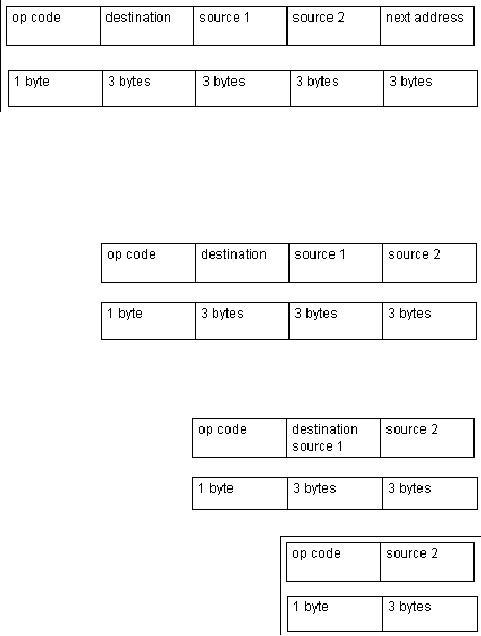
Discussion4-address
instruction
�
The code size
is 13
bytes
(1+3+3+3+3
= 13
bytes)
�
Number of
bytes
accessed
from memory is 22 (13 bytes
for instruction fetch + 6
bytes for source
operand
fetch + 3 bytes for storing
destination operand = 22 bytes)
Note
that there is no need for an
additional memory access for
the operand corresponding
to the
next instruction, as it has
already been brought into
the CPU during
instruction
fetch.
3-address
instruction
�
The code size is 10
bytes
(1+3+3+3
= 10 bytes)
�
Number of bytes
accessed
from
memory is 22
(10
bytes for instruction
fetch
+ 6 bytes
for source operand fetch + 3 bytes
for storing destination operand =
19
bytes)
2-address
instruction
�
The code size is 7 bytes
(1+3+3 = 7
bytes)
�
Number of bytes
accessed from
memory is
16(7 bytes for
instruction
fetch + 6
bytes for source operand
fetch + 3
bytes for storing
destination operand = 16
bytes)
1-address
instruction
�
The code size is 4 bytes
(1+3= 4 bytes)
�
Number of bytes accessed
from memory is 7
(4 bytes
for instruction fetch + 3
bytes for source
operand
fetch + 0 bytes for storing
destination operand = 7 bytes)
Page
34
Last
Modified: 01-Nov-06
Advanced Computer
Architecture-CS501
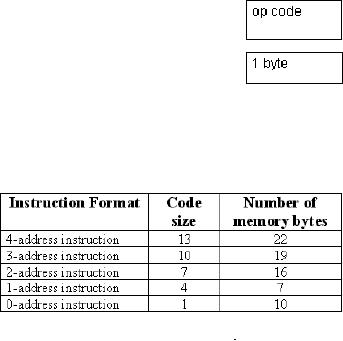
0-address
instruction
�
The code size is 1
byte
�
Number of bytes accessed
from memory is 10
(1 byte
for instruction fetch + 6
bytes for source operand fetch +
3
bytes
for storing destination operand = 10
bytes)
The
following table summarizes
this information
HALF
ADDRESSES
In the
preceding discussion we
have
talked
about memory addresses.
This
discussion
also applies to CPU
registers.
However, to specify/
encode
a CPU
register, less number of
bits is
required
as compared to the memory addresses.
Therefore, these addresses
are also called
"half-addresses".
An instruction that specifies one memory
address and one CPU
register
can be
called as a 1�-address
instruction
Example
mov
al, [34h]
THE
PRACTICAL SITUATION
Real
machines are not as simple
as the classifications presented above.
In fact, these
machines
have a mixture of 3, 2, 1, 0, and
1�-address instructions. For
example, the
VAX 11
includes instructions from
all classes.
CLASSIFICATION
OF MACHINES ON THE BASIS OF
OPERAND
AND
RESULT LOCATION:
A
distinction between machines can be
made on the basis of the ALU
instructions;
whether
these instructions use data
from the memory or not. If
the ALU instructions
use
only
the CPU registers for the
operands and result, the
machine type is called "load-
store". Other
machines may have a mixture
of register-memory, or
memory-memory
instructions.
The
number of memory operands
supported by a typical ALU instruction
may vary from
0 to
3.
Example
The
SPARC, MIPS, Power PC,
ALPHA: 0 memory addresses,
max operands allowed =
3
X86,
68x series: 1 memory
address, max operands
allowed = 2
LOAD-
STORE MACHINES
These
machines are also called the
register-to-register machines. They
typically use the
1�
address instruction format.
Only the load and store
instructions can access
the
memory.
The load instruction fetches
the required data from
the memory and
temporarily
stores it
in the CPU registers. Other
instructions may use this
data from the
CPU
registers.
Then later, the results can
be stored back into the memory by
the store
instruction.
Most RISC computers fall
under this category of
machines.
Advantages
(of register-register
instructions)
Register-register
instructions use 0 memory
operands out of a total of 3 operands.
The
advantages
of such a scheme is:
� The
instructions are simple and
fixed in length
Page
35
Last
Modified: 01-Nov-06
Advanced Computer
Architecture-CS501
� The
corresponding code generation
model is simple
� All
instructions take similar number of
clock cycles for
execution
Disadvantages
(register-register instructions)
� The
instruction count is higher;
the number of instructions
required to complete a
particular
task is more as separate instructions
will be required for load and
store
operations
of the memory
� Since the
instruction size is fixed, the
instructions that do not
require all fields
waste
memory bits
Register-memory
machines
In
register-memory machines, some
operands are in the memory
and some are in
registers. These
machines typically employ 1 or 1�
address instruction format, in
which
one of
the operands is an accumulator or a
general-purpose CPU registers.
Advantages
Register-memory
operations use one memory operand
out of a total of two operands.
The
advantages
of this instruction format
are
� Operands in
the memory can be accessed
without having to load these
first
through a
separate load
instruction
� Encoding
is easy due to the elimination of
the need of loading operands
into
registers
first
� Instruction
bit usage is relatively
better, as more instructions
are provided per
fixed
number of bits
Disadvantages
� Operands
are not equivalent since one operand
may have two functions
(both
source operand and
destination operand), and the source
operand may be
destroyed
� Different
size encoding for memory and registers
may restrict the number
of
registers
� The
number of clock cycles per
instruction execution vary,
depending on the
operand
location operand fetch from
memory is slow as compared to operands
in
CPU
registers
Memory-Memory
Machines
In
memory-memory machines, all
three of the operands (2 source
operands and a
destination
operand) are in the memory.
If one of the operands is being
used both as a
source and a
destination, then the
2-address format is used.
Otherwise, memory-memory
machines
use 3-address formats of
instructions.
Advantages
� The
memory-memory instructions are
the most compact instruction
where
encoding
wastage is minimal.
� As
operands are fetched from
and stored in the memory directly, no
CPU registers
are
wasted for temporary
storage
Disadvantages
� The
instruction size is not fixed;
the large variation in
instruction sizes
makes
decoding
complex
� The
cycles per instruction execution also
vary from instruction to
instruction
Page
36
Last
Modified: 01-Nov-06
Advanced Computer
Architecture-CS501
�
Memory
accesses are
generally
slow, so
too many references
cause
performance degradation
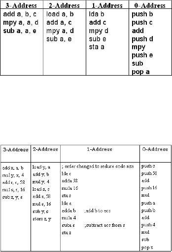
Example
1
The
expression a =
(b+c)*d e is
evaluated
with the 3, 2, 1, and 0-
address
machines to provide a
comparison
of their advantages and disadvantages
discussed above. The
instructions
shown in
the table are the
minimal instructions required to
evaluate the given
expression.
Note
that these are not
machine language instructions,
rather the pseudo-code.
Example
2
The
instruction z =
4(a +b) 16(c+58) is with
the 3, 2, 1, and 0-address machines in
the
table.
Functional
classification
of
instruction
sets:
Instructions
can be classified into
the
following
four categories based
on
their
functionality.
� Data
processing
� Data
storage (main memory)
� Data
movement (I/O)
�
Program flow
control
These are
discussed in detail
� Data
processing
Data processing
instructions are the ones
that perform some
mathematical or logical
operation
on some operands. The Arithmetic
Logic Unit performs these
operations,
therefore
the data processing instructions can also
be called ALU instructions.
� Data
storage (main
memory)
The
primary storage for the
operands is the main memory.
When an operation needs to
be
performed
on these operands, these can be
temporarily brought into the
CPU registers,
and after
completion, these can be stored back to
the memory. The instructions
for data
access
and storage between the
memory and the CPU can be categorized as
the data
storage
instructions.
� Data
movement (I/O)
The
ultimate sources of the data
are input devices e.g. keyboard.
The destination of
the
data is
an output device, for
example, a monitor, etc. The
instructions that enable
such
operations
are called data movement
instructions.
� Program
flow control
A CPU
executes instructions sequentially,
unless a program flow-change
instruction is
encountered.
This flow change, also
called a branch, may be
conditional or unconditional.
In case
of a conditional branch, if the
branch condition is met, the
target address is loaded
into
the program counter.
ADDRESSING
MODES:
Addressing
modes are the different
ways in which the CPU
generates the address
of
operands. In
other words, they provide
access paths to memory locations and
CPU
registers.
Effective
address
Page
37
Last
Modified: 01-Nov-06
Advanced Computer
Architecture-CS501
An
"effective address" is the
address (binary bit pattern)
issued by the CPU to
the
memory.
The CPU may use
various ways to compute the
effective address. The
memory
may
interpret the effective
address differently under
different situations.
COMMONLY
USED ADDRESSING MODES
Some
commonly used addressing
modes are explained
below.
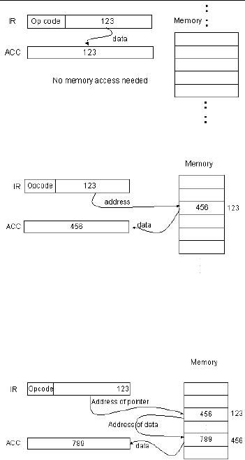
Immediate
addressing mode
In this
addressing mode, data is the
part of the instruction
itself, and so there is no need
of
address
calculation. However, immediate
addressing mode is used to hold
source
operands
only; cannot be used for
storing results. The range of
the operands is limited
by
the
number of bits available for
encoding the operands in the
instruction; for n bit
fields,
the range
is -2(n-1) to +(2(n-1)-1).
Example:
lda 123
In this
example, the
immediate
operand,
123, is loaded onto
the
accumulator.
No address calculation is
required.
Direct
Addressing Mode
The
address of the operand is
specified
as a
constant, and this constant
is
coded as
part of the instruction. The
address space that can be
accessed is limited
address
space by
the operand field size (2operand field
size locations).
Example:
lda [123]
As shown
in the figure, the address
of
the
operand is stored in the
instruction.
The
operand is then fetched from
that
memory
address.
Indirect
Addressing Mode
The
address of the location
where the
address
of the data is to be found
is
stored in
the instruction as the
operand.
Thus,
the operand is the address of a
memory location, which holds
the address of the
operand.
Indirect addressing mode can access a
large address space (2memory word
size
locations).
To fetch the operand in this
addressing mode, two memory
accesses are
required.
Since memory accesses are
slow, this is not efficient
for frequent memory
accesses.
The indirect addressing
mode
may be
used to implement
pointers.
Example:
lda [[123]]
As shown
in the figure, the address
of
the
memory location that holds
the
address
of the data in the memory
is
part of
the instruction.
Register
(Direct) Addressing
Mode
The
operand is contained in a CPU register,
and the address of this
register is encoded in
the
instruction. As no memory access is
needed, operand fetch is efficient.
However,
there
are only a limited number of
CPU registers available, and this
imposes a limitation
on the
use of this addressing
mode.
Page
38
Last
Modified: 01-Nov-06
Advanced Computer
Architecture-CS501
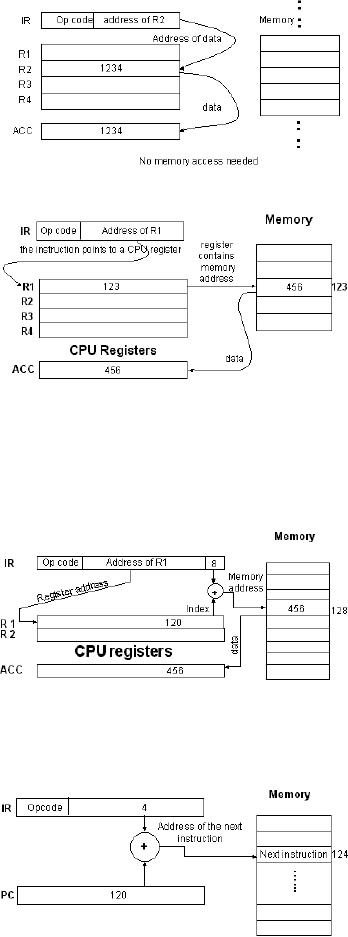
Example:
lda R2
This
load instruction specifies the
address of the register and
the operand is fetched
from
this
register. As is clear from
the diagram, no memory
access is involved in
this
addressing
mode.
REGISTER
INDIRECT
ADDRESSING
MODE
In the
register indirect mode,
the
address
of memory location
that
contains
the operand is in a CPU
register.
The address of this
CPU
register
is encoded in the instruction.
A
large
address space can be
accessed
using
this addressing mode (2register
size
locations).
It involves fewer
memory
accesses
compared to indirect addressing.
Example:
lda [R1]
The
address of the register
that
contains
the address of
memory
location
holding the operand
is
encoded
in the instruction. There
is
one
memory access
involved.
Displacement
addressing mode
The
displacement-addressing mode is
also
called based or
indexed
addressing
mode. Effective memory
address is calculated by adding a
constant (which is
usually a
part of the instruction) to
the value in a CPU register.
This addressing mode is
useful
for accessing arrays. The
addressing mode may be called
`indexed' in the
situation
when
the constant refers to the
first element of the array
(base) and the register
contains
the
`index'. Similarly, `based'
refers to the situation when
the constant refers to the
offset
(displacement)
of an array element with
respect to the first
element. The address of
the
first
element is stored in a register.
Example:
lda [R1 + 8]
In this
example, R1 is the address
of
the
register that holds a
memory
address,
which is to be used to
calculate
the effective address of
the
operand.
The constant (8) is added
to
this
address held by the register
and
this
effective address is used
to
retrieve
the operand.
Relative
addressing mode
The
relative addressing mode is similar to
the indexed addressing mode
with the
exception
that the PC holds the
base address. This allows
the storage of memory
operands
at a fixed offset from
the
current
instruction and is useful
for
`short'
jumps.
Example:
jump 4
Page
39
Last
Modified: 01-Nov-06
Advanced Computer
Architecture-CS501
The
constant offset (4) is a
part of the instruction, and it is
added to the address held
by
the
Program Counter.
RISC
and CISC architectures:
Generally,
computers can be classified as being
RISC machines or CISC
machines. These
concepts
are explained in the
following discussion.
RISC
(Reduced instruction set
computers)
RISC is
more of a philosophy of computer design
than a set of architectural
features. The
underlying
idea is to reduce the number and
complexity of instructions. However,
new
RISC
machines have some
instructions that may be
quite complex and the number
of
instructions
may also be large. The
common features of RISC
machines are
� One
instruction per clock
period
This is
the most important feature
of the RISC machines. Since
the program execution
depends
on throughput and not on individual
execution time, this feature
is achievable by
using
pipelining and other techniques. In
such a case, the goal is
issuing an average of
one
instruction per cycle without
increasing the cycle
time.
� Fixed
size instructions
Generally,
the size of the instructions is 32
bits.
� CPU
accesses memory only for
Load and Store operations
This
means that all the
operands are in the CPU
registers at the time these
are used in an
instruction.
For this purpose, they are
first brought into the
CPU registers from
the
memory
and later stored back through the
load and store operation
respectively.
� Simple
and few addressing modes
The
disadvantage associated with using
complex addressing modes is
that complex
decoding
is required to calculate these
addresses, which reduces the
processor
performance
as it takes significant time.
Therefore, in RISC machines,
few simple
addressing
modes are used.
� Less
work per
instruction
As the
instructions are simple,
less work is done per instruction, and
hence the clock
period T
can be reduced.
� Improved
usage of delay slots
A `delay
slot' is the waiting time
for a load or store operation to
access memory or for
a
branch
instruction to access the
target instruction. RISC
designs allow the execution
of
the
next instruction after these
instructions are issued. If the
program or compiler
places
an
instruction in the delay
slot that does not
depend on the result of the
previous
instruction,
the delay slot can be used
efficiently. For the
implementation of this
feature,
improved
compilers are required that
can check the dependencies of
instructions before
issuing
them to utilize the delay
slots.
� Efficient
usage of Pre-fetching and Speculative
Execution Techniques
Pre-fetching
and speculative execution techniques
are used with a pipelined
architecture.
Instruction
pipelining means having
multiple instructions in different
stages of execution
as
instructions are issued
before the previous
instruction has completed
its execution;
pipelining
will be studied in detail later.
The RISC machines examine
the instructions to
check if
operand fetches or branch instructions
are involved. In such a
case, the operands
or the
branch target instructions can be
`pre-fetched'. As instructions are
issued before
the
preceding instructions have
completed execution, the
processor will not know in
case
Page
40
Last
Modified: 01-Nov-06
Advanced Computer
Architecture-CS501
of a
conditional branch instruction,
whether the condition will be
met and the branch
will
be taken
or not. But instead of waiting
for this information to be
available, the branch
can
be
"speculated" as taken or not
taken, and the instructions can be
issued. Later if the
speculation
is found to be wrong, the
results can be discarded and actual
target
instructions
can be issued. These techniques help
improve the performance of
processors.
CISC
(Complex Instruction Set
Computers)
The
complex instruction set
computers does not have an
underlying philosophy.
The
CISC
machines have resulted from
the efforts of computer
designers to efficiently
utilize
memory
and minimize execution time,
yet add in more instruction
formats and
addressing
modes. The common attributes of
CISC machines are discussed
below.
� More
work per
instruction
This
feature was very useful at
the time when memory was
expensive as well as slow;
it
allows
the execution of compact
programs with more
functionality per instruction.
� Wide
variety of addressing
modes
CISC
machines support a number of
addressing modes, which
helps reduce the
program
instruction
count. There are 14
addressing modes in MC68000 and 25 in
MC68020.
� Variable
instruction lengths and execution times
per instruction
The
instruction size is not fixed and so
the execution times vary
from instruction to
instruction.
� CISC
machines attempt to reduce the "semantic
gap"
`Semantic
gap' is the gap between
machine level instruction
sets and high-level
language
constructs.
CISC designers believed that
narrowing this gap by
providing complicated
instructions
and complex-addressing modes would
improve performance. The
concept
did
not work because compiler
writes did not find
these "improvements" useful.
The
following
are some of the disadvantages of
CISC machines.
� Clock
period T, cannot be reduced
beyond a certain
limit
When
more capabilities are added
to an instruction the CPU
circuits required for
the
execution
of these instructions become
complex. This results in
more stages of logic
circuitry
and adds propagation delays in
signal paths.
This in
turn places a limit on the
smallest possible value of T and hence,
the maximum
value of
clock frequency.
� Complex
addressing modes delay operand fetch from
memory
The
operand fetch is delayed because
more time is required to
decode complex
instructions.
� Difficult
to make efficient use of
speedup techniques
These
speedup techniques
include
� Pipelining
� Pre-fetching
(Intel 8086 has a 6 byte
queue)
� Super scalar
operation
� Speculative
execution
Page
41
Last
Modified: 01-Nov-06
Table of Contents:
- Computer Architecture, Organization and Design
- Foundations of Computer Architecture, RISC and CISC
- Measures of Performance SRC Features and Instruction Formats
- ISA, Instruction Formats, Coding and Hand Assembly
- Reverse Assembly, SRC in the form of RTL
- RTL to Describe the SRC, Register Transfer using Digital Logic Circuits
- Thinking Process for ISA Design
- Introduction to the ISA of the FALCON-A and Examples
- Behavioral Register Transfer Language for FALCON-A, The EAGLE
- The FALCON-E, Instruction Set Architecture Comparison
- CISC microprocessor:The Motorola MC68000, RISC Architecture:The SPARC
- Design Process, Uni-Bus implementation for the SRC, Structural RTL for the SRC instructions
- Structural RTL Description of the SRC and FALCON-A
- External FALCON-A CPU Interface
- Logic Design for the Uni-bus SRC, Control Signals Generation in SRC
- Control Unit, 2-Bus Implementation of the SRC Data Path
- 3-bus implementation for the SRC, Machine Exceptions, Reset
- SRC Exception Processing Mechanism, Pipelining, Pipeline Design
- Adapting SRC instructions for Pipelined, Control Signals
- SRC, RTL, Data Dependence Distance, Forwarding, Compiler Solution to Hazards
- Data Forwarding Hardware, Superscalar, VLIW Architecture
- Microprogramming, General Microcoded Controller, Horizontal and Vertical Schemes
- I/O Subsystems, Components, Memory Mapped vs Isolated, Serial and Parallel Transfers
- Designing Parallel Input Output Ports, SAD, NUXI, Address Decoder , Delay Interval
- Designing a Parallel Input Port, Memory Mapped Input Output Ports, wrap around, Data Bus Multiplexing
- Programmed Input Output for FALCON-A and SRC
- Programmed Input Output Driver for SRC, Input Output
- Comparison of Interrupt driven Input Output and Polling
- Preparing source files for FALSIM, FALCON-A assembly language techniques
- Nested Interrupts, Interrupt Mask, DMA
- Direct Memory Access - DMA
- Semiconductor Memory vs Hard Disk, Mechanical Delays and Flash Memory
- Hard Drive Technologies
- Arithmetic Logic Shift Unit - ALSU, Radix Conversion, Fixed Point Numbers
- Overflow, Implementations of the adder, Unsigned and Signed Multiplication
- NxN Crossbar Design for Barrel Rotator, IEEE Floating-Point, Addition, Subtraction, Multiplication, Division
- CPU to Memory Interface, Static RAM, One two Dimensional Memory Cells, Matrix and Tree Decoders
- Memory Modules, Read Only Memory, ROM, Cache
- Cache Organization and Functions, Cache Controller Logic, Cache Strategies
- Virtual Memory Organization
- DRAM, Pipelining, Pre-charging and Parallelism, Hit Rate and Miss Rate, Access Time, Cache
- Performance of I/O Subsystems, Server Utilization, Asynchronous I/O and operating system
- Difference between distributed computing and computer networks
- Physical Media, Shared Medium, Switched Medium, Network Topologies, Seven-layer OSI Model