 |
SRC Exception Processing Mechanism, Pipelining, Pipeline Design |
| << 3-bus implementation for the SRC, Machine Exceptions, Reset |
| Adapting SRC instructions for Pipelined, Control Signals >> |
Advanced Computer
Architecture-CS501
Advanced
Computer Architecture
Lecture
No. 18
Reading
Material
Vincent
P. Heuring & Harry F. Jordan
Chapter
4
Computer
Systems Design and Architecture
4.8
Summary
�
SRC
Exception Processing
Mechanism
�
Introduction
to Pipelining
�
Complications
Related to Pipelining
�
Pipeline
Design Requirements
Correction:
Please
note that the phrase
"instruction fetch" should be
used where the
speaker
has used "instruction
interpretation".
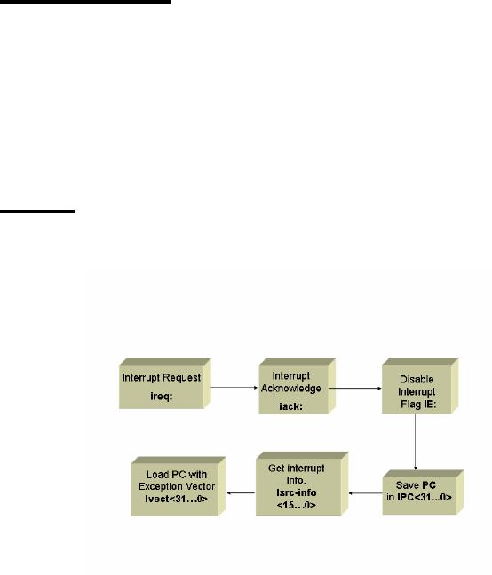
SRC
Exception Processing Mechanism
The
following tables on the next
few pages summarize the
changes needed in the
SRC
description
for including
exceptions:
Behavioral
RTL for Exception Processing
Page
201
Last
Modified: 01-Nov-06

Advanced Computer
Architecture-CS501
Instruction_Fetch:=
(!Run&Strt:
Run ← 1,
Start
Normal
Fetch
Run &
!(ireq&IE):(IR ←M[PC],
PC ← PC +
4;
Instruction_Execution),
Interrupt,
PC copied
Run&(ireq&IE):
(IPC ← PC<31..0>,
II is loaded
with the info.
II<15..0>
←
Isrc_info<15..0>,
PC loaded
with new address
IE ← 0: PC ← Ivect<31..0>,
iack
←
1;
iack ← 0),
Instruction_Fetch);
Additional
Instructions to Support
Interrupts
Mnemonic
Behavioral
RTL
Meaning
R[ra]<15..0>
←
II<15..0>,
svi
(op=16)
Save II
and IPC
R[rb]
←
IPC<31..0>;
II<15..0>
←
R[ra]<15..0>,
ri
(op=17)
Restore II and
IPC
IPC<31..0>
←
R[rb];
IE ← 1;
een
(op=10)
Exception
enable
IE ← 0;
edi
(op=11)
Exception
disable
PC ← IPC, IE
←
1;
rfi
(op=30)
Return
from interrupt
Structural
RTL for the Fetch Phase including
Exception Processing
Step
Structural
RTL for the 1-bus
SRC
!(ireq&IE): (MA
←
PC, C
←
PC +
4);
T0
(ireq&IE):
(IPC ← PC,II← Isrc_info,
IE ← 0,PC
←
(22α 0)�(Isrc_vect<7..0>)
00, iack ← 1;
iack
←
0,
End) ;
MD ← M[MA], PC ← C;
T1
IR ← MD;
T2
T3
Instruction_Execution;
Combining
the RTL for Reset and
Exception
Page
202
Last
Modified: 01-Nov-06
Advanced Computer
Architecture-CS501
Instruction_Fetch:=
Events
(Run&!Rst&!(ireq&IE):(IR
←
M[PC], PC
←
PC+4;
Normal
Fetch
Instruction_Execution),
Run&Rst:
(Rst ←0 , IE ← 0, PC ← 0;
Instruction_Fetch),
Soft
Reset
!Run&Strt:
(Run ←1, PC ← 0,
R[0..31] ← 0;
Instruction_Fetch),
Hard
Reset
Interrupt
Run&!Rst&(ireq&IE):
(IPC ← PC<31..0>,
II<15..0>
←Isrc_info<15..0>,
IE ←
0, PC
←
Ivect<31..0>,
iack
←
1;
iack ← 0;
Instruction_Fetch) );
Introduction
to Pipelining
Pipelining
is a technique of overlapping multiple
instructions in time. A
pipelined
processor
issues a new instruction
before the previous
instruction completes. This
results
in a
larger number of operations
performed per unit of time.
This approach also results in
a more
efficient usage of all the
functional units present in the
processor, hence leading to
a higher
overall throughput. As an example,
many shorter integer
instructions may be
executed
along with a longer floating
point multiply instruction,
thus employing the
floating
point unit simultaneously
with the integer
unit.
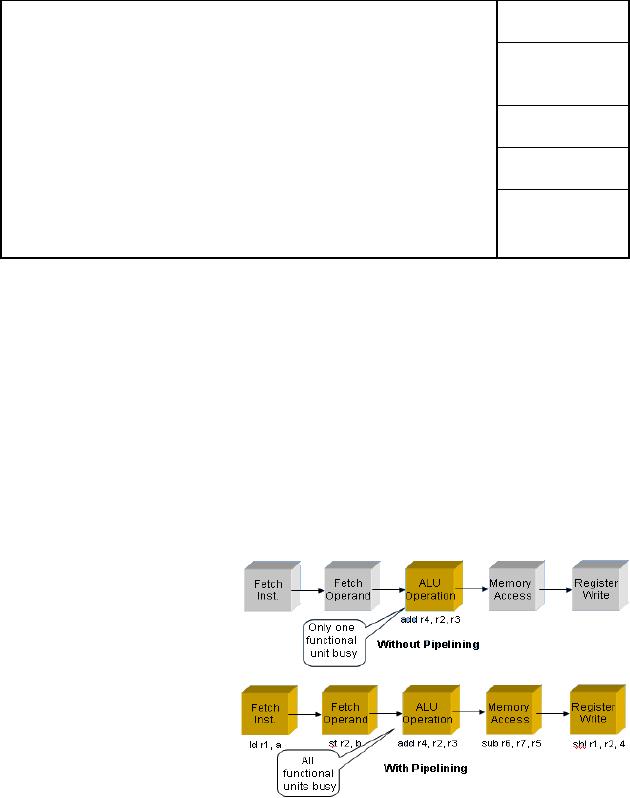
Executing machine
instructions with and without
pipelining
We start
by assuming that a given
processor can be split in to five
different stages as
shown in
the diagram below,
and as
explained later in
this
section.
Each stage receives
its
input from the
previous
stage and
provides its result
to the
next stage. It can be
easily
seen from the
diagram
that in
case of a non-
pipelined
machine there is a
single
instruction add
r4, r2,
r3
being
processed at a given
time,
while in a pipelined
machine,
five
different
instructions
are being processed
simultaneously. An implied assumption in
this case is
that at
the end of each stage, we
have some sort of a storage
place (like temporary
registers)
to hold the results of the
present stage till they are
used by the next
stage.
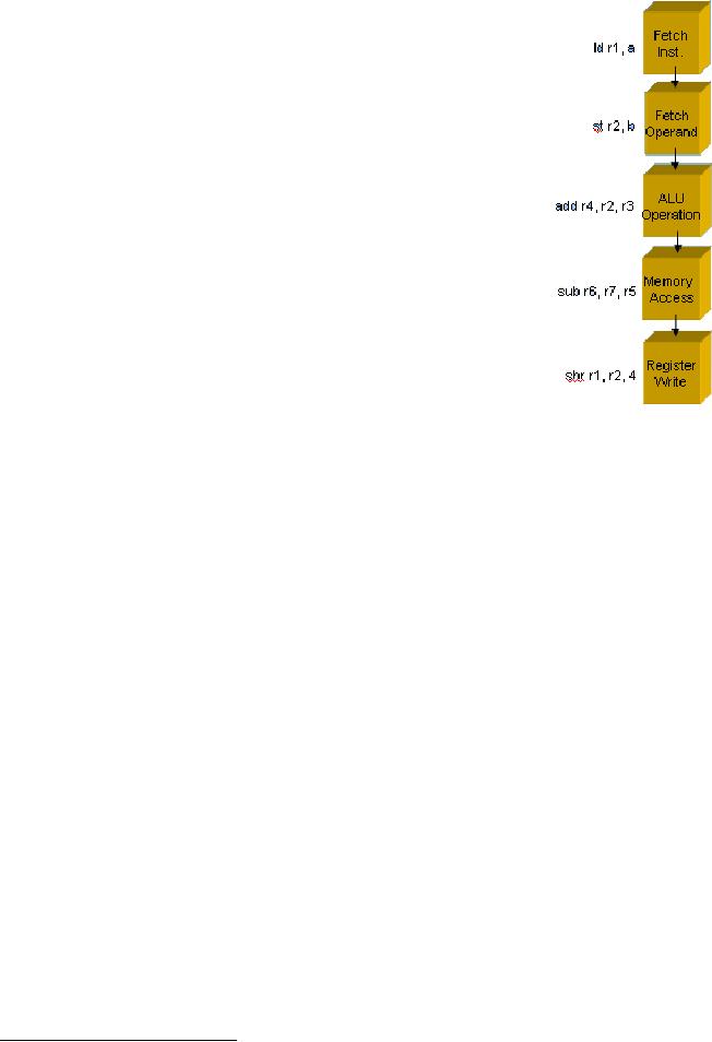
Description of
the Pipeline Stages
In the
following paragraphs, we discuss the
pipeline stages mentioned in
the previous
example.
Page
203
Last
Modified: 01-Nov-06
Advanced Computer
Architecture-CS501
1.
Instruction fetch
As the
name implies, the instruction is
fetched from the
instruction
memory in this stage. The
fetched instruction
bits
are
loaded into a temporary pipeline
register.
2.
Instruction decode/operand
fetch
In this
stage the operands for
the instruction are fetched
from
the
register file. If the
instruction is add
r1, r2, r3 the
registers r2 and r3
will be read into the
temporary pipeline
registers.
3.
ALU5 operation
In this
stage, the fetched operand
values are fed into
the ALU
along
with the function which is
required such as
addition,
subtraction,
etc. The result is stored
into temporary
pipeline
registers. In
case of a memory access such
as a load or a store
instruction,
the ALU calculates the
effective memory
address
in this
stage.
4.
Memory access
For a
load instruction, a memory
read operation takes place.
For a store instruction, a
memory
write operation is performed. If
there is no memory access
involved in the
instruction,
this stage is simply
bypassed.
5. Register
write
The
result is stored in the destination
register in this
stage.
Latency
& throughput
Latency
is defined as the time
required to process a single
instruction, while throughput
is
defined
as the number of instructions
processed per second. Pipelining cannot
lower the
latency
of a single instruction; however, it
does increase the
throughput. With respect
to
the
example discussed earlier, in a
non-pipelined machine there
would be one instruction
processed
after an average of 5 cycles,
while in a pipelined machine,
instructions are
completed
after each and every cycle
(in the steady-state, of course!!!).
Hence, the overall
time
required to execute the
program is reduced.
Remember
that the performance gain in
a pipeline is limited by the
slowest stage in the
pipeline.
Complications
Related to Pipelining
Certain
complications may arise from
pipelining a processor. They are
explained below:
Data
dependence
This
refers to the situation when
an instruction in one stage of the
pipeline uses the
results
of an
instruction in the previous
stage. As an example let us
consider the following
two
instructions
5
The ALU
is also called the ALSU in
some cases, in particular,
where its "shifting" capabilities
need to be
highlighted.
ALSU stands for Arithmetic
Logic Shift Unit.
Page
204
Last
Modified: 01-Nov-06
Advanced Computer
Architecture-CS501
...
S1:
add r3, r2, r1
S2:
sub r4, r5, r3
...
There is
a data-dependence among the above
two instructions. The
register R3 is being
written
to in the instruction S1,
while it is being read from
in the instruction S2. If
the
instruction
S2 is executed before instruction S1 is
completed, it would result in
an
incorrect
value of R3 being
used.
Resolving
the dependency
There
are two methods to remedy
this situation:
1.
Pipeline stalls
These are
inserted into the pipeline
to block instructions from
entering the pipeline
until
some
instructions in the later
part of the pipeline have
completed execution. Hence
our
modified
code would become
...
S1:
add r3, r2, r1
stall6
stall
stall
S2:
sub r4, r5, r3
...
2.
Data forwarding
When
using data forwarding, special
hardware is added to the processor,
which allows
the
results of a particular pipeline
stage to be transferred directly to
another stage in the
pipeline
where they are required.
Data may be forwarded directly
from the execute
stage
of one
instruction to the decode
stage of the next
instruction. Considering the
above
example,
S1 will be in the execute stage
when S2 will be decoded. Using a
comparator
we can
determine that the
destination operand of S1 and source operand of S2 are
the
same.
So, the result of S1 may be
directly forwarded to the
decode stage.
Other
complications include the
"branch delay" and the "load
delay". These are
explained
below:
Branch
delay
Branches
can cause problems for
pipelined processors. It is difficult to
predict whether a
branch
will be taken or not before
the branch condition is tested.
Hence if we treat a
branch
instruction like any normal
instruction, the instructions
following the branch
will
be loaded in
the stages following the
stage which carries the
branch instruction. If
the
branch is
taken, then those instructions
would need to be removed
from the pipeline and
their
effects if any, will have to be
undone. An alternate method is to
introduce stalls, or
nop
instructions,
after the branch
instruction.
Load
delay
6
A pipeline stall
can be achieved by using the
nop
instruction.
Page
205
Last
Modified: 01-Nov-06
Advanced Computer
Architecture-CS501
Another
problem surfaces when a value is loaded
into a register and then
immediately
used in
the next operation. Consider
the following
example:
...
S1:
load r2, 34(r1)
S2:
add r5, r2, r3
...
In the
above code, the "correct"
value of R2 will be available after
the memory access
stage in
the instruction S1. Hence
even with data forwarding a
stall will need to be placed
between
S1 and S2, so that S2 fetches
its operands only after
the memory access for
S1
has
been made.
Pipeline
Design Requirements
For a
pipelined design, it is important that
the overall meaning of the
program remains
unchanged,
i.e., the program should
produce the same results as
it would produce on a
non-pipelined
machine. It is also preferred that
the data and instruction
memories are
separate
so that instructions may be
fetched while the register
values are being
stored
and/or
loaded from data memory.
There should be a single
data path so as not
to
complicate
the flow of instructions and
maintain the order of
program execution.
There
should be
a three port register file
so that if the register
write and register read
stages
overlap,
they can be performed in parallel,
i.e., the two register
operands may be read
while
the destination register may
be written. The data should
be latched in between
each
pipeline
stage using temporary
pipeline registers. Since the clock
cycle depends on the
slowest
pipeline stage, the ALU
operations must be able to complete
quickly so that the
cycle
time is not increased for
the rest of the
pipeline.
Designing
a pipelined implementation
In this
section we will discuss the
various steps involved in
designing a pipeline.
Broadly
speaking
they may be categorized into
three parts:
1.
Adapting the instructions to pipelined
execution
The
instruction set of a non-pipelined
processor is generally different
from that of a
pipelined
processor. The instructions in a
pipelined processor should
have clear and
definite
phases, e.g., add
r1, r2, r3. To
execute this instruction,
the processor must
first
fetch it
from memory, after which it
would need to read the
registers, after which
the
actual
addition takes place followed by
writing the results back to
the destination
register.
Usually
register-register architecture is adopted
in the case of pipelined
processors so that
there
are no complex instructions
involving operands from both
memory and registers.
An
instruction like add
r1, r2, a would
need to execute the memory
access stage before
the
operands may be fed to the
ALU. Such flexibility is not
available in a pipelined
architecture.
2.
Designing the pipelined data
path
Page
206
Last
Modified: 01-Nov-06
Advanced Computer
Architecture-CS501
Once a
particular instruction set
has been chosen, an appropriate data
path needs to be
designed
for the processor. The data
path is a specification of the
steps that need to be
followed
to execute an instruction. Consider
our two examples
above
For
the instruction add
r1, r2, r3: Instruction
Fetch Register Read
Execute Register
Write,
whereas
for the instruction add
r1, r2, a (remember
a represents a memory address), we
have
Instruction
Fetch Register Read
Memory Access Execute
Register Write
The
data path is defined in
terms of registers placed in between
these stages. It specifies
how
the data will flow through
these registers during the
execution of an instruction.
The
data
path becomes more complex if
forwarding or bypassing mechanism is
added to the
processor.
3.
Generating control
signals
Control
signals are required to
regulate and direct the flow
of data and instruction
bits
through
the data path. Digital
logic is required to generate
these control
signals.
Page
207
Last
Modified: 01-Nov-06
Table of Contents:
- Computer Architecture, Organization and Design
- Foundations of Computer Architecture, RISC and CISC
- Measures of Performance SRC Features and Instruction Formats
- ISA, Instruction Formats, Coding and Hand Assembly
- Reverse Assembly, SRC in the form of RTL
- RTL to Describe the SRC, Register Transfer using Digital Logic Circuits
- Thinking Process for ISA Design
- Introduction to the ISA of the FALCON-A and Examples
- Behavioral Register Transfer Language for FALCON-A, The EAGLE
- The FALCON-E, Instruction Set Architecture Comparison
- CISC microprocessor:The Motorola MC68000, RISC Architecture:The SPARC
- Design Process, Uni-Bus implementation for the SRC, Structural RTL for the SRC instructions
- Structural RTL Description of the SRC and FALCON-A
- External FALCON-A CPU Interface
- Logic Design for the Uni-bus SRC, Control Signals Generation in SRC
- Control Unit, 2-Bus Implementation of the SRC Data Path
- 3-bus implementation for the SRC, Machine Exceptions, Reset
- SRC Exception Processing Mechanism, Pipelining, Pipeline Design
- Adapting SRC instructions for Pipelined, Control Signals
- SRC, RTL, Data Dependence Distance, Forwarding, Compiler Solution to Hazards
- Data Forwarding Hardware, Superscalar, VLIW Architecture
- Microprogramming, General Microcoded Controller, Horizontal and Vertical Schemes
- I/O Subsystems, Components, Memory Mapped vs Isolated, Serial and Parallel Transfers
- Designing Parallel Input Output Ports, SAD, NUXI, Address Decoder , Delay Interval
- Designing a Parallel Input Port, Memory Mapped Input Output Ports, wrap around, Data Bus Multiplexing
- Programmed Input Output for FALCON-A and SRC
- Programmed Input Output Driver for SRC, Input Output
- Comparison of Interrupt driven Input Output and Polling
- Preparing source files for FALSIM, FALCON-A assembly language techniques
- Nested Interrupts, Interrupt Mask, DMA
- Direct Memory Access - DMA
- Semiconductor Memory vs Hard Disk, Mechanical Delays and Flash Memory
- Hard Drive Technologies
- Arithmetic Logic Shift Unit - ALSU, Radix Conversion, Fixed Point Numbers
- Overflow, Implementations of the adder, Unsigned and Signed Multiplication
- NxN Crossbar Design for Barrel Rotator, IEEE Floating-Point, Addition, Subtraction, Multiplication, Division
- CPU to Memory Interface, Static RAM, One two Dimensional Memory Cells, Matrix and Tree Decoders
- Memory Modules, Read Only Memory, ROM, Cache
- Cache Organization and Functions, Cache Controller Logic, Cache Strategies
- Virtual Memory Organization
- DRAM, Pipelining, Pre-charging and Parallelism, Hit Rate and Miss Rate, Access Time, Cache
- Performance of I/O Subsystems, Server Utilization, Asynchronous I/O and operating system
- Difference between distributed computing and computer networks
- Physical Media, Shared Medium, Switched Medium, Network Topologies, Seven-layer OSI Model