 |
Arithmetic Logic Shift Unit - ALSU, Radix Conversion, Fixed Point Numbers |
| << Hard Drive Technologies |
| Overflow, Implementations of the adder, Unsigned and Signed Multiplication >> |

Advanced Computer
Architecture-CS501
________________________________________________________
Advanced
Computer Architecture
Lecture
No. 34
Reading
Material
Vincent
P. Heuring & Harry F. Jordan
Chapter
6
Computer
Systems Design and Architecture
6.1,
6.2
Summary
·
Introduction
to ALSU
·
Radix
Conversion
·
Fixed
Point Numbers
·
Representation
of Numbers
·
Multiplication
and Division using Shift
Operation
·
Unsigned
Addition Operation
Introduction
to ALSU 29
ALSU is a
combinational circuit so inside an
ALSU, we have AND, OR, NOT
and other
different
gates combined together in
different ways to perform
addition, subtraction,
and,
or,
not, etc. Up till now, we
consider ALSU as a "black
box" which takes two
operands, a
and b, at
the input and has c at the
output. Control signals
whose values depend upon
the
opcode of
an instruction were associated
with this black
box.
In order
to understand the operation of
the ALSU, we need to
understand the basis of
the
representation
of the numbers. For example,
a designer needs to specify how
many bits
are
required for the source
operands and how many will be
needed for the
destination
operand
after an operation to avoid
overflow and truncation.
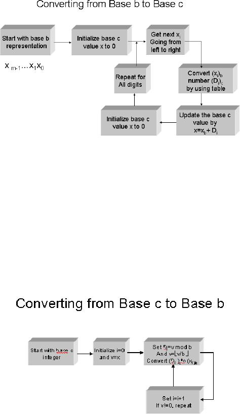
Radix
Conversion
Now we
will consider the conversion of
numbers from a representation in one
base to
another.
As human works with base 10
and computers with base 2,
this radix conversion
operation
is important to discuss here. We will
use base c notion for
decimal
representation
and base b for any other
base. The following figure
shows the algorithm
of
converting
from base b to base
c:
29
In our
discussion we have used ALU
and ALSU for the
same thing. We use ALSU when
the shift aspect
also
needs to be emphasized.
Page
327
Last
Modified: 01-Nov-06
Advanced Computer
Architecture-CS501
________________________________________________________
Example
1
Convert
the hexadecimal number B316 to base 10.
Solution
According
to the above algorithm,
X=0
X= x+B
(=11) =11
X=16*11+3=
179
Hence
B316=17910
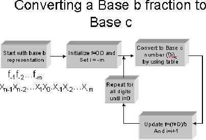
The
following figure shows the
algorithm of converting from
base c to base b:
Page
328
Last
Modified: 01-Nov-06
Advanced Computer
Architecture-CS501
________________________________________________________
Example
2
Convert
39010 to base
16.
Solution
According
to the above algorithm
390/16
=24( rem=6), x0=6
24/16=
1(rem=8), x1=8, x2=1
Thus
39010=18616
Fixed
Point Numbers
Suppose
we have a number with a
radix point. For example, in
16.12, there are two
digits
on the
left side and two digits on
the right of the decimal
point. In this case, the
radix
point is
a decimal point because we
suppose that given number is
a decimal number.
If we
have an integer, then this
decimal point will be on the
right most position
i.e.
1612.0
and if it is in fraction then decimal
will be at the left most
position i.e. 0.1612
There
are situations when we shift
the position of the radix
point. Shifting of the
radix
point
towards left or right is
called scaling and we could
have multiplication with a
base
or
division by a base
respectively.
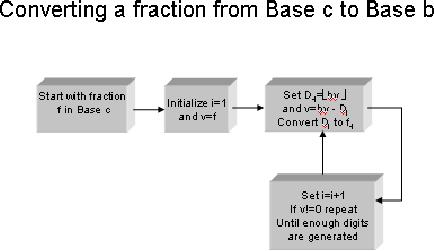
The
following figure shows the
algorithm of converting a base b
fraction to base c:
Example
3
Convert
(.4cd) 16
to Base
10.
Solution
F=0
F=(0+13)/16=0.8125
Page
329
Last
Modified: 01-Nov-06
Advanced Computer
Architecture-CS501
________________________________________________________
F=(0.8125+12)/16=0.80078125
F=(0.80078125+4)/16=(0.3000488)
10
The
following figure shows the
algorithm of converting fraction
from base c to base
b:
Example
4
Convert
0.2410 to base 2.
Solution
0.24*2=0.48,
f-1=0
0.48*2=0.96,
f-2=0
0.96*2=1.92,
f-3=1
0.92*2=1.84,
f-4=1
0.84*2=1.68,
f-5=1,...
Thus
0.2410 =(0.00111) 2
Representation
of Numbers
There
are four possibilities to represent
integers.
1.
Sign
magnitude form
2.
Radix
complement form
3.
Diminished
radix complement form
4.
Biased
representation
Sign
magnitude form
·
This is the simplest
form for representing a signed
number
· A
symbol representing the sign
of the number is appended to
the left of the
number
Page
330
Last
Modified: 01-Nov-06
Advanced Computer
Architecture-CS501
________________________________________________________
·
This
representation complicates the
arithmetic operations
Radix
complement form
·
This is the most
common representation.
·
Given an m-digit base b
number x, the radix
complement of x is
xc = ( bm x) mod bm
·
This representation makes
the arithmetic operations
much easier.
Diminished
radix complement form
·
The diminished radix
complement of an m-digit number x
is
xc'=bm
-1-
x
·
This complement is easier to
compute than the radix
complement.
·
The two complement
operations are interconvertible,
as
xc= ( xc'+1)mod bm
Table
6.1 of the text book
shows the complement
representation of negative numbers
for
radix
complement and diminished radix
complement form:
Table
6.2 of the text book
shows the base 2 complement
representation for 8-bit 2's
and
1's
complement numbers.
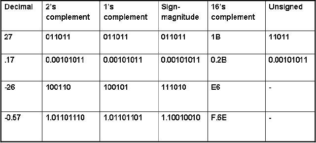
Example
5
The
following table shows the
decimal values in 2's
complement, 1's complement,
sign
magnitude,
16's complement and in unsigned
form:
Multiplication
and Division using Shift
Operation
Page
331
Last
Modified: 01-Nov-06
Advanced Computer
Architecture-CS501
________________________________________________________
Shift
left and shift right are
two important operations
used for various purposes.
One
typical
example could be multiplication or
division by base b. The
following examples
explain
multiplication and division by using
shift operation.
Example
6
·
6x4
001102 x 410 =110002=2410
Overflow
would occur if we will use 4
bits instead of 5 bits
here.
·
60/16
01111002/1610=00000112=310
The
fractional portion of the
result is lost.
Example
7
·
-6x4
-6 =
(11010) 2
-6x4 =
(01000) 2=8
which is wrong!
using
less no. of bits might
change sign
So, -6 =
(111010) 2
-6x4 =
(101000) 2
=
-24
Example
8
Multiplication
and division of negative
numbers
Solution
-24x2
-24=
(101000) 2
-24x2=
(010100)2
= 20
-24x2=
(110100)2
=
-12
Changing
the size of the
number,
24=
011000 (n=6) to 00011000 (n=8)
-24=
101000 (n=6) to 11101000 (n=8)
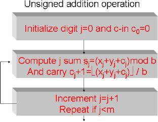
Unsigned
Addition Operation
The
following diagram shows the
digit
wise
procedure for adding m-digit
base
b
numbers, x and y:
Example
9
Unsigned
addition in base 2 and
base16.
Solution
Page
332
Last
Modified: 01-Nov-06
Advanced Computer
Architecture-CS501
________________________________________________________
Base
16 addition
Base
2 addition
A B 4 2 16
100011 2
+ 3 1 C 1 16
+ 011011 2
carry 0 1
0 0
carry
000110
sum
D D 0 3 16
sum
111110 2
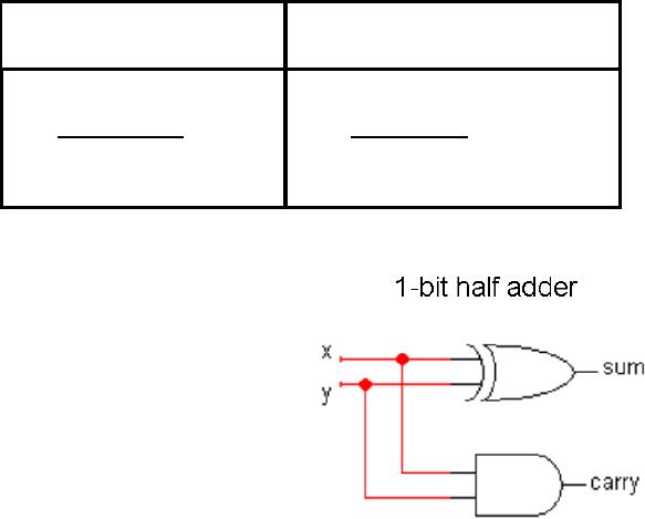
The
following diagram shows the
logic
circuit
for 1-bit half adder. It
takes two
1-bit
inputs x and y and as a result, we
get a
1-bit sum and a 1-bit carry.
This
circuit
is called a half adder
because it
does
not take care of input
carry. In
order to
take into account the effect
of
the
input carry, a 1-bit full
adder is
used
which is also shown in the
figure.
We can
add two m-bit numbers
by
using a
circuit which is made
by
cascading
m 1-bit full adders.
The
situation, when addition of
unsigned m-bit numbers
results in an m+1 bit
number, is
called
overflow. Overflow is treated as
exception in some processors and
the overflow
flag is
used to record the status of
the result.
Page
333
Last
Modified: 01-Nov-06
Table of Contents:
- Computer Architecture, Organization and Design
- Foundations of Computer Architecture, RISC and CISC
- Measures of Performance SRC Features and Instruction Formats
- ISA, Instruction Formats, Coding and Hand Assembly
- Reverse Assembly, SRC in the form of RTL
- RTL to Describe the SRC, Register Transfer using Digital Logic Circuits
- Thinking Process for ISA Design
- Introduction to the ISA of the FALCON-A and Examples
- Behavioral Register Transfer Language for FALCON-A, The EAGLE
- The FALCON-E, Instruction Set Architecture Comparison
- CISC microprocessor:The Motorola MC68000, RISC Architecture:The SPARC
- Design Process, Uni-Bus implementation for the SRC, Structural RTL for the SRC instructions
- Structural RTL Description of the SRC and FALCON-A
- External FALCON-A CPU Interface
- Logic Design for the Uni-bus SRC, Control Signals Generation in SRC
- Control Unit, 2-Bus Implementation of the SRC Data Path
- 3-bus implementation for the SRC, Machine Exceptions, Reset
- SRC Exception Processing Mechanism, Pipelining, Pipeline Design
- Adapting SRC instructions for Pipelined, Control Signals
- SRC, RTL, Data Dependence Distance, Forwarding, Compiler Solution to Hazards
- Data Forwarding Hardware, Superscalar, VLIW Architecture
- Microprogramming, General Microcoded Controller, Horizontal and Vertical Schemes
- I/O Subsystems, Components, Memory Mapped vs Isolated, Serial and Parallel Transfers
- Designing Parallel Input Output Ports, SAD, NUXI, Address Decoder , Delay Interval
- Designing a Parallel Input Port, Memory Mapped Input Output Ports, wrap around, Data Bus Multiplexing
- Programmed Input Output for FALCON-A and SRC
- Programmed Input Output Driver for SRC, Input Output
- Comparison of Interrupt driven Input Output and Polling
- Preparing source files for FALSIM, FALCON-A assembly language techniques
- Nested Interrupts, Interrupt Mask, DMA
- Direct Memory Access - DMA
- Semiconductor Memory vs Hard Disk, Mechanical Delays and Flash Memory
- Hard Drive Technologies
- Arithmetic Logic Shift Unit - ALSU, Radix Conversion, Fixed Point Numbers
- Overflow, Implementations of the adder, Unsigned and Signed Multiplication
- NxN Crossbar Design for Barrel Rotator, IEEE Floating-Point, Addition, Subtraction, Multiplication, Division
- CPU to Memory Interface, Static RAM, One two Dimensional Memory Cells, Matrix and Tree Decoders
- Memory Modules, Read Only Memory, ROM, Cache
- Cache Organization and Functions, Cache Controller Logic, Cache Strategies
- Virtual Memory Organization
- DRAM, Pipelining, Pre-charging and Parallelism, Hit Rate and Miss Rate, Access Time, Cache
- Performance of I/O Subsystems, Server Utilization, Asynchronous I/O and operating system
- Difference between distributed computing and computer networks
- Physical Media, Shared Medium, Switched Medium, Network Topologies, Seven-layer OSI Model