 |
| Information Systems |

VU
Information
System (CS507)
LESSON
24
Symbols
used for flow
charts
24.1
Symbols
The
symbols have already been
briefly stated in the previous Lesson.
Following would explain
these
symbols
in detail.
Arrow
The symbol
indicates the flow of
the
procedure
being explained. The
usual
direction of the flow of
a
procedure or
system is from left
to
right or
top to bottom.
Terminator
·This is
the symbol used to
indicate
the start
and finish of the
process.
·Only one
flow line is used in
conjunction with
terminator symbol.
100

VU
Information
System (CS507)
Process
· This symbol is used
to indicate a
activity
undertaken or action done.
· For
instance
Make
sub-totals
Create
file
· Only one flow line
should come
out from a
process symbol.
Decision
·The symbol is
used when a choice
can
be made between
the options
available.
·Such options
are mutually
exclusive.
·Only one flow
line should enter a
decision
symbol, but two or three
flow
lines, one
for each possible
answer,
should
leave the decision
symbol.
<0
<0
=0
>0
<0
101
VU
Information
System (CS507)
Connectors
·If the
flowchart becomes complex,
it is better to
use connector symbols
to reduce
the number of flow
lines.
·Avoid the
intersection of flow
lines
if you want to
make it more
effective
and better
way of communication.
Predefined
Process
·Where two
or more steps are
repeated in a
standard sequence,
they
collectively are
presented
through
this symbol.
·This
represents a named
process
consisting of more
than a couple of
operations or
steps which must
have been
identified separately.
102

VU
Information
System (CS507)
Single
Document
Refers to a
hard copy being
created
as a result of a
process.
Off-Page
Connector
Use to
connect remote
flowchart
portions on
different pages. Only one
flow line
enters or exits.
Input / Output
Operation
· The symbol is used
whenever the system
receives an input or
generates an output..
E.g.
Display
message
"How
many
Read
Hours
hours did
you
work?"
Output
Operation
Input
Operation
· A single
flow line enters and a single
line
exits.
24.2
Good Practices
Recommended
practices for flow
charts:
·
Ensure
that the flowchart has a logical
start and finish.
103

VU
Information
System (CS507)
·
In drawing a
proper flowchart, all
necessary steps that are a
part of process should be listed
out
in logical
order.
·
The
flowchart should be clear, neat
and easy to follow. There should
not be any room
for
ambiguity in
understanding the flowchart.
·
It is
useful to test the validity of the
flowchart.
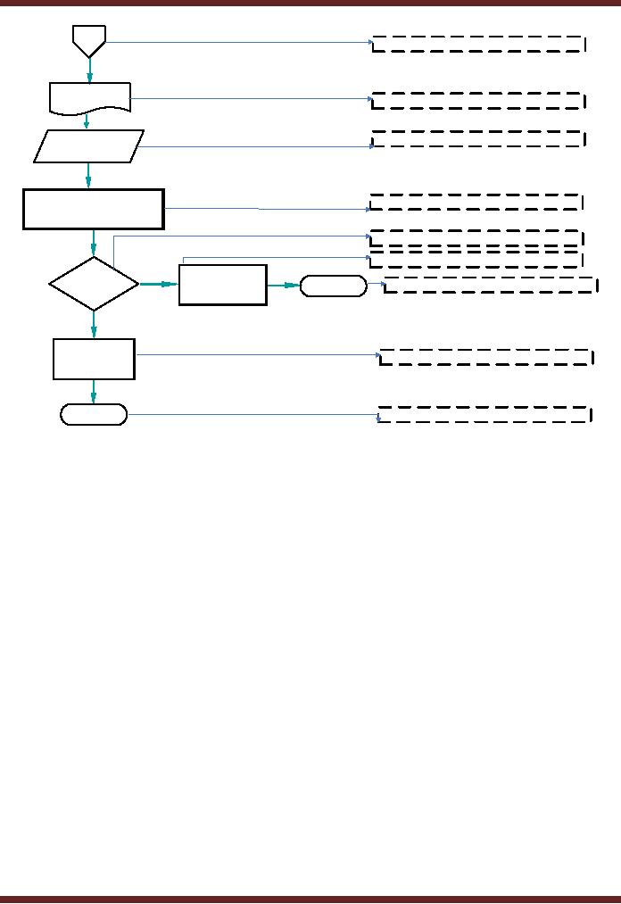
Following
can be seen as a comprehensive
example of how the symbols of
flow charts as defined above
are
used.
As
shown in the above diagram, the
bidding process starts with
issuing prequalification document.
The
purpose
is to seek preliminary information so as
to decide whether the bidder qualifies
for submitting a
bid.
Where the information does
not support the criteria, the bidder is
not further allowed to
proceed.
Other
wise, the Request for
Proposal is issued to the
bidder.
Since
the process cannot be summarized in one
page, it is continued to the next
page by using an off
page
connector.
104
VU
Information
System (CS507)
P#1
Off-Page
Connector
RFP
Document
Document
Used for
Input / Output
Receive
RFP
Evaluate on
following basis
Process
1.
Technical
2.
Financial
Decision
Process
Intimate
Are
the
N
unsuccessful
Terminator
End
criteria
met
bidders
Y
Award
Process
Contract
End
Start/End of a
process known as
Terminator
On the
next page, another off page
connector is used to give reference of the
page from which it is
being
continued.
The process continues with
issuance of RFP document and
receiving the filled
RFP
document.
An evaluation is made of the bidders on
technical and financial bases. In
case the criteria are
not
met, the unsuccessful bidders
are intimated and process
for this class ends. Where
the criteria are
met,
contract is awarded. The process
termination is shown by using the
terminator symbol.
Advantages
·
The
benefits of flowcharts are as
follows:
·
Communication
Flowcharts are better way of
communicating the logic of a system to
all
concerned.
Flowcharts are more focused
on decision making and activities relating
thereto taken in
a set
of relevant processes.
·
Proper
documentation Program flowcharts serve as a
good program documentation, which
is
needed
for various purposes.
Advantages
·
Efficient
Coding: The
flowcharts act as a guide or blueprint
during the systems analysis
and
program development
phase.
·
Proper
Debugging: The
flowchart helps in locating and
correcting errors (Also
called
debugging).
·
Efficient
Program Maintenance: The
maintenance of operating program becomes
easy with
the
help of flowchart.
24.3
Data Flow Diagram
"A
data flow diagram (DFD) is a
graphical representation of the "flow" of
data through an
105

VU
Information
System (CS507)
information
system."
The
purpose of data flow
diagrams is to provide a linking bridge
between users and systems
developers.
The
data flow diagrams
are:
·
Graphical,
eliminating thousands of
words;
·
Hierarchical,
showing systems at any level of detail;
and
They
have less jargon, allowing
user understanding and reviewing.
Data
flow diagrams facilitate users to
understand how the system
operate. DFD's also help
developers to
better
understand the system which
helps in avoiding delays in
proper designing, development, etc.
of
projects.
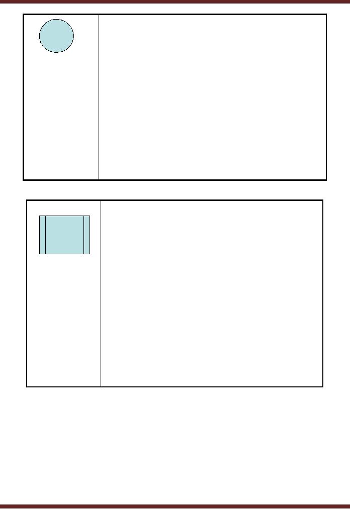
Following
are the symbols of used in the making of
flow charts.
Entity
represents
sources of data
received
by the
system or destinations of
the
data
produced by the
system.
E.g.
Customers,
suppliers, purchase
department
If the
entity is repeated in the
DFD, the
same symbol
with the addition of a bar
in
the left
hand corner is used and looks
like.
106

VU
Information
System (CS507)
Process
represents an
activity that
transforms or
manipulates the data
(combines,
reorders, converts,
etc.)
E.G
Calculate
Calculate
Tax
Gross
Salary
Deductions
Data
Flow
represents
movement of data
Data
Store
Represents
the permanent or
temporary
data
storage site. E.g.
Employee
Master File
If this
storage site is repeated in
the DFD,
the same
symbol with the addition of
a bar
in the
left hand corner is used
and looks
like.
Employee
Master File
107
- Need for information, Sources of Information: Primary, Secondary, Tertiary Sources
- Data vs. Information, Information Quality Checklist
- Size of the Organization and Information Requirements
- Hierarchical organization, Organizational Structure, Culture of the Organization
- Elements of Environment: Legal, Economic, Social, Technological, Corporate social responsibility, Ethics
- Manual Vs Computerised Information Systems, Emerging Digital Firms
- Open-Loop System, Closed Loop System, Open Systems, Closed Systems, Level of Planning
- Components of a system, Types of Systems, Attributes of an IS/CBIS
- Infrastructure: Transaction Processing System, Management Information System
- Support Systems: Office Automation Systems, Decision Support Systems, Types of DSS
- Data Mart: Online Analytical Processing (OLAP), Types of Models Used in DSS
- Organizational Information Systems, Marketing Information Systems, Key CRM Tasks
- Manufacturing Information System, Inventory Sub System, Production Sub System, Quality Sub system
- Accounting & Financial Information Systems, Human Resource Information Systems
- Decision Making: Types of Problems, Type of Decisions
- Phases of decision-making: Intelligence Phase, Design Phase, Choice Phase, Implementation Phase
- Planning for System Development: Models Used for and Types of System Development Life-Cycle
- Project lifecycle vs. SDLC, Costs of Proposed System, Classic lifecycle Model
- Entity Relationship Diagram (ERD), Design of the information flow, data base, User Interface
- Incremental Model: Evaluation, Incremental vs. Iterative
- Spiral Model: Determine Objectives, Alternatives and Constraints, Prototyping
- System Analysis: Systems Analyst, System Design, Designing user interface
- System Analysis & Design Methods, Structured Analysis and Design, Flow Chart
- Symbols used for flow charts: Good Practices, Data Flow Diagram
- Rules for DFD’s: Entity Relationship Diagram
- Symbols: Object-Orientation, Object Oriented Analysis
- Object Oriented Analysis and Design: Object, Classes, Inheritance, Encapsulation, Polymorphism
- Critical Success Factors (CSF): CSF vs. Key Performance Indicator, Centralized vs. Distributed Processing
- Security of Information System: Security Issues, Objective, Scope, Policy, Program
- Threat Identification: Types of Threats, Control Analysis, Impact analysis, Occurrence of threat
- Control Adjustment: cost effective Security, Roles & Responsibility, Report Preparation
- Physical vs. Logical access, Viruses, Sources of Transmissions, Technical controls
- Antivirus software: Scanners, Active monitors, Behavior blockers, Logical intrusion, Best Password practices, Firewall
- Types of Controls: Access Controls, Cryptography, Biometrics
- Audit trails and logs: Audit trails and types of errors, IS audit, Parameters of IS audit
- Risk Management: Phases, focal Point, System Characterization, Vulnerability Assessment
- Control Analysis: Likelihood Determination, Impact Analysis, Risk Determination, Results Documentation
- Risk Management: Business Continuity Planning, Components, Phases of BCP, Business Impact Analysis (BIA)
- Web Security: Passive attacks, Active Attacks, Methods to avoid internet attacks
- Internet Security Controls, Firewall Security SystemsIntrusion Detection Systems, Components of IDS, Digital Certificates
- Commerce vs. E-Business, Business to Consumer (B2C), Electronic Data Interchange (EDI), E-Government
- Supply Chain Management: Integrating systems, Methods, Using SCM Software
- Using ERP Software, Evolution of ERP, Business Objectives and IT
- ERP & E-commerce, ERP & CRM, ERP– Ownership and sponsor ship
- Ethics in IS: Threats to Privacy, Electronic Surveillance, Data Profiling, TRIPS, Workplace Monitoring